Nissan Pathfinder: Fuel System - Fuel System (Periodic Maintenance). Fuel Level Sensor Unit (Disassembly and Assembly)
Fuel System (Periodic Maintenance) Nissan Pathfinder SUV
Inspection
Inspect fuel lines, fuel filler cap, and fuel tank for improper attachment, leaks, cracks, damage, loose connections, chafing or deterioration.
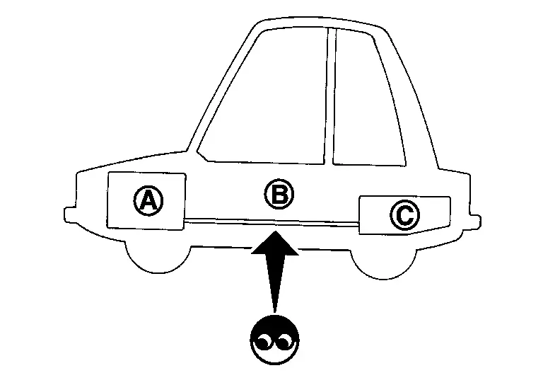
| (A) | : Engine |
| (B) | : Fuel line |
| (C) | : Fuel tank |
If necessary, repair or replace damaged parts.
Quick Connector
CAUTION:
-
After connecting fuel tube quick connectors, check that quick connectors are secure.
-
Ensure that connector and resin tube never contact any adjacent parts.
-
Quick connector (1) can be disconnected when the tabs (F) are depressed completely. Do not twist it more than necessary.
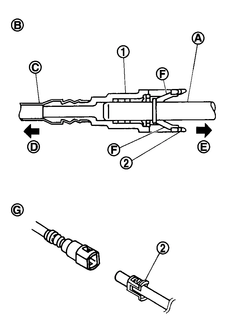
(B) : Connection (cross-section) (D) : To under floor fuel line (E) : To fuel tank (G) : Disconnection -
Do not use any tools to disconnect quick connector.
-
Keep resin tube (C) away from heat. Be especially careful when welding near the resin tube.
-
Prevent acid liquid such as battery electrolyte, etc. from getting on resin tube.
-
Do not bend or twist resin tube during installation and disconnection.
-
Do not remove the remaining retainer (2) on hard tube (or the equivalent) (A) except when resin tube or retainer is replaced.
-
When resin tube or hard tube (or the equivalent) is replaced, also replace retainer with new one.
-
To keep the connecting portion clean and to avoid damage and foreign materials, cover them completely with plastic bags (A) or something similar.

Fuel Level Sensor Unit (Disassembly and Assembly) Nissan Pathfinder SUV
Disassembly and Assembly
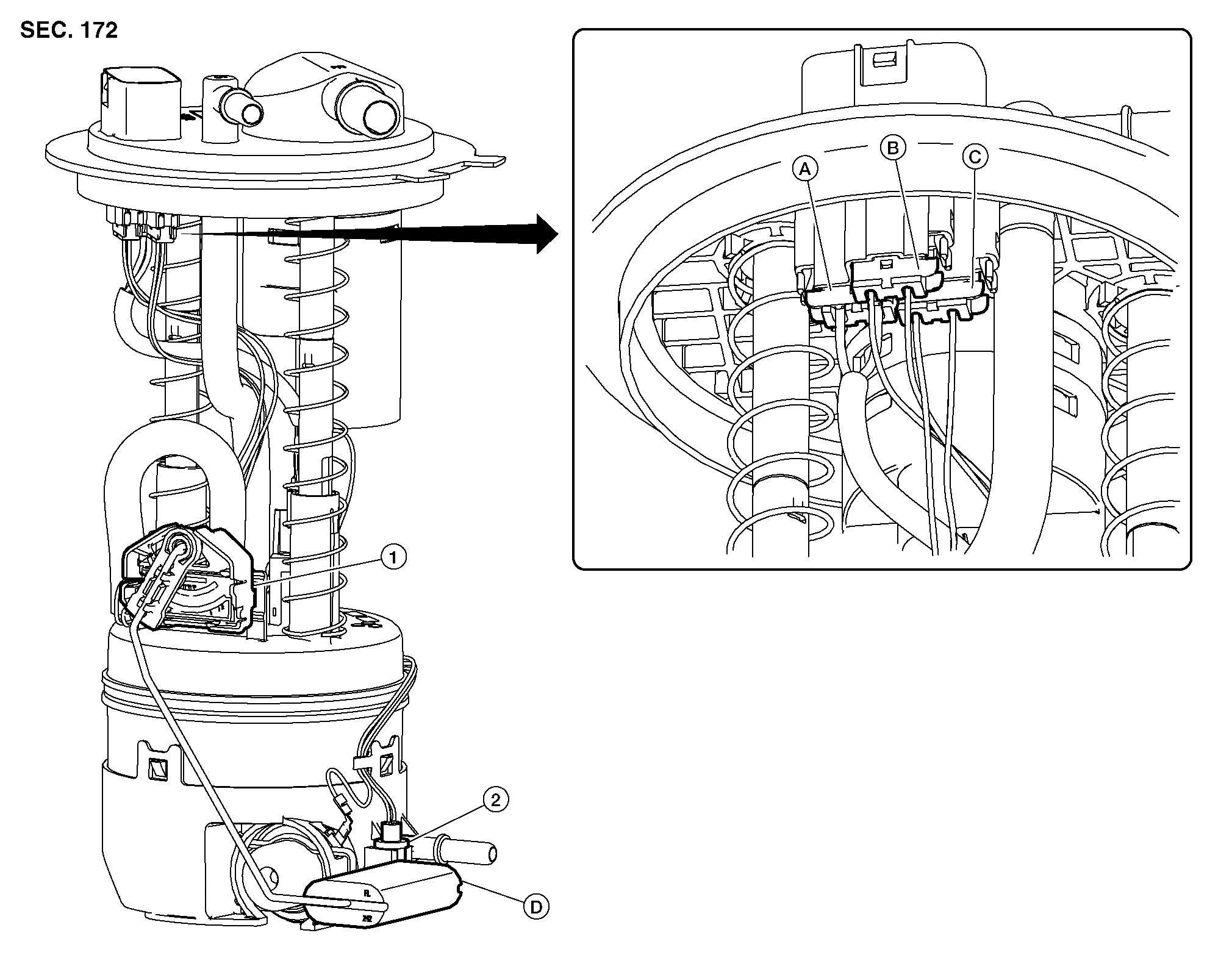
| 1. | Fuel level sensor unit | 2. | Fuel tank temperature sensor | A. | Fuel level sensor unit harness connector |
| B. | Fuel pump harness connector | C. | Fuel tank temperature sensor harness connector | D. | Float arm assembly |
Disassembly
 NOTE:
NOTE:
Before disassembly, note the proper placement of the wires to the correct terminals and correct wire routing to the terminals.
Disconnect the fuel level sensor unit harness connector (A) and the fuel tank temperature sensor harness connector (C). Press the tabs on the terminals to release the locking tabs.
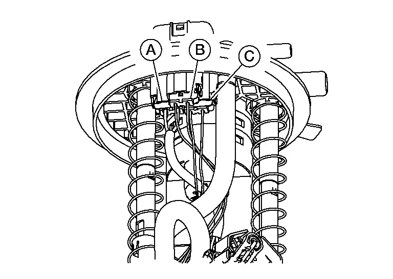
| (B) | : Fuel pump harness connector |
Release the two clips and remove the fuel tank temperature sensor from the pump assembly.
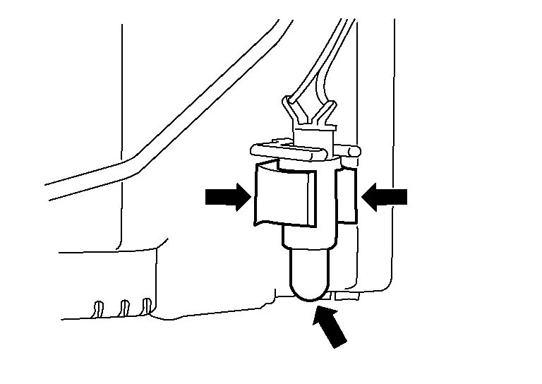
Release the tab and slide the fuel level sensor unit and float arm assembly up to remove.
Assembly
Assembly is in the reverse order of disassembly.
 NOTE:
NOTE:
-
Ensure proper placement of the wires to the correct terminals and correct wire routing to the terminals.
-
After connecting terminals, ensure they are securely locked and can not be pulled out.
-
When installing the fuel level sensor unit, push down until the tab is locked into place.

Nissan Pathfinder (R53) 2022-2026 Service Manual
Fuel System (Periodic Maintenance). Fuel Level Sensor Unit (Disassembly and Assembly)
Contact Us
Nissan Pathfinder Info Center
Email: info@nipathfinder.com
Phone: +1 (800) 123-4567
Address: 123 Pathfinder Blvd, Nashville, TN 37214, USA
Working Hours: Mon–Fri, 9:00 AM – 5:00 PM (EST)
