Nissan Pathfinder: Steering Control System - Eps Control Unit (Ecu Diagnosis Information. Removal and Installation)
Eps Control Unit (Ecu Diagnosis Information) Nissan Pathfinder 5th Gen
Values on the Diagnosis Tool
 NOTE:
NOTE:
The following table includes information (items) inapplicable to this Nissan Pathfinder vehicle: For information (items) applicable to this vehicle, refer to CONSULT display items.
| Monitor item | Data monitor | ||
|---|---|---|---|
| Condition | Display value | ||
| BATTERY VOLT | Engine running | 10.5 V – 16 V | |
| STEERING TORQUE | Engine running | Steering wheel: Not steering (There is no steering force) | Approx. 0.0 Nm |
| Steering wheel: Left turn | Positive value (Nm) | ||
| Steering wheel: Right turn | Negative value (Nm) | ||
| STEERING ANGLE SIGNAL | Steering wheel: Not steering (There is no steering force) | Approx. 0 deg | |
| Steering wheel: Right turn | Positive value (deg) | ||
| Steering wheel: Left turn | Negative value (deg) | ||
| MOTOR CURRENT | Engine running | Steering wheel: Not steering (There is no steering force) | Approx. 0 A |
| Steering wheel: Right or left turn | Displays consumption current of EPS motor (A) | ||
| MOTOR TORQUE COMMAND | Engine running | Steering wheel: Not steering (There is no steering force) | Approx. 0 A |
| Steering wheel: Right turn | Positive value (A) | ||
| Steering wheel: Left turn | Negative value (A) | ||
| C/U TEMP | Engine running | Displays temperature of inside of EPS control unit [°C] | |
| ASSIST LEVEL | Engine running | 100%*1 | |
| Nissan Pathfinder Vehicle SPEED | Vehicle stopped | 0.00 km/h | |
| While driving |
Approximately equal to the indication on speedometer*2 (inside of ±10%) |
||
| WARNING LAMP | Power steering warning lamp: ON | On | |
| Power steering warning lamp: OFF | OFF | ||
| STEERING ANGLE SENSOR STATUS | Malfunction in steering angle sensor. | ABNORMAL | |
| No Malfunction in steering angle sensor. | NORMAL | ||
| ENGINE STATUS | Engine not running | STOP | |
| Engine running | RUN | ||
| Engine cranking | CRANK | ||
| HEAT PROTECT STATUS | Ignition switch ON or Engine running | No over heat. | NORMAL |
| Over heat. | PRTECT | ||
| ST TORQUE FLAG | — | Off | |
| STOP/START STATUS | Power steering system status | INACT | |
| Command steering angle | - |
Displays but not used |
|
| Current steering angle | - |
Displays but not used |
|
| PA status | - |
Displays but not used |
|
| PA ST angle valid status | - |
Displays but not used |
|
| Target motor current | Engine running | Steering wheel: Not steering (There is no steering force) | Approx. 0 A |
| Steering wheel: Right turn | Positive value (A) | ||
| Steering wheel: Left turn | Negative value (A) | ||
| ST speed valid status | - |
Displays but not used |
|
| Control gain | - |
Displays but not used |
|
| Steering control request status | - |
Displays but not used |
|
| Steering force judgment | - |
Displays but not used |
|
| EPS status | - |
Displays but not used |
|
| EPS control (ADAS) | - |
Displays but not used |
|
| Steering wheel | - |
Displays but not used |
|
 NOTE:
NOTE:
 NOTE:
NOTE:
 NOTE:
NOTE:
 NOTE:
NOTE:
 NOTE:
NOTE:
 NOTE:
NOTE:
 NOTE:
NOTE:
 NOTE:
NOTE:
 NOTE:
NOTE:
 NOTE:
NOTE:
 NOTE:
NOTE:
*1: Normally displays 100%. In case of an excessive stationary steering, the assist curvature gradually falls. However, it returns to 100% when left standing.
*2: It is not a malfunction, though it might not be corresponding just after ignition switch ON.
Reference Value
TERMINAL LAYOUT
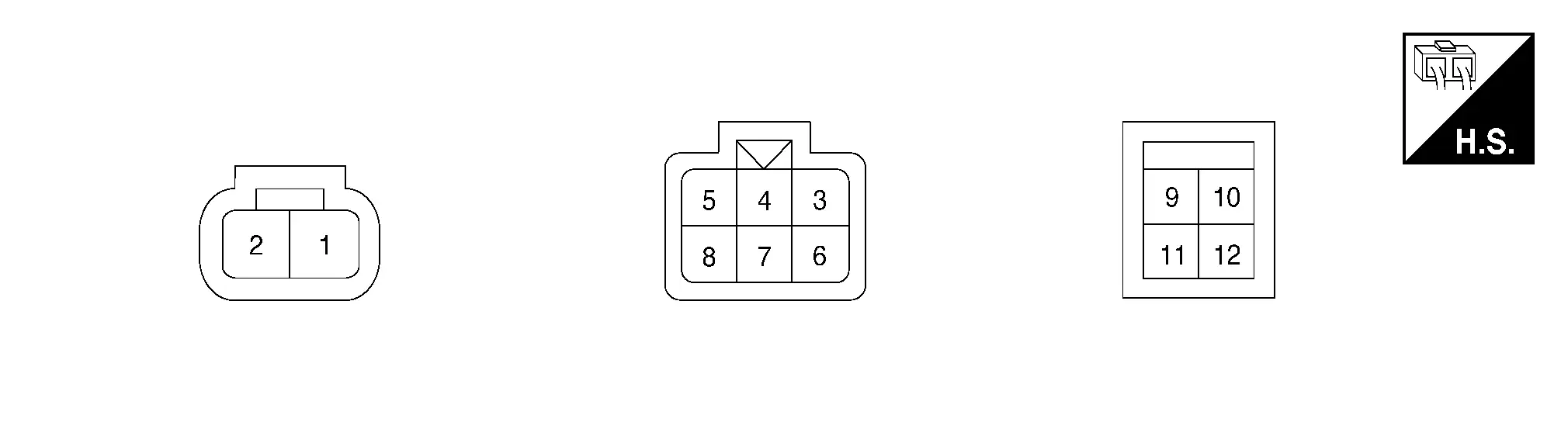
PHYSICAL VALUES
|
Terminal No. (Wire Color) | Description | Condition |
Value (Approx.) | |||
|---|---|---|---|---|---|---|
| + | − | Signal name | Input/Output | |||
|
1 (B) |
Ground | Ground | — | Always | 0 V | |
|
2 (W) |
Ground | Battery power supply | Input | Always | Battery voltage | |
|
3 (BR) |
Ground | Ignition power supply | Input | Ignition switch: ON | Battery voltage | |
| Ignition switch: OFF | 0 V | |||||
|
4 (GR) |
— | CAN-High | Input/Output | — | — | |
|
5 (G) |
— | CAN-Low | Input/Output | — | — | |
|
9 (B) |
Ground | Ground | — | Always | 0 V | |
|
10 (Y) |
— | Sub signal | Input/Output | — | — | |
|
11 (W) |
— | Main signal | Input/Output | — | — | |
|
12 (R) |
Ground | Power supply | Input | Always | Battery voltage | |
Fail-safe
-
If any malfunction occurs in the system and control module detects the malfunction, power steering warning lamp on combination meter turns ON to indicate system malfunction.
-
When power steering warning lamp is ON, the system enters into a manual steering state. (Control turning force steering wheel becomes heavy.)
| DTC | Fail-safe condition |
|---|---|
| C1601–01 | Manual steering state |
| C1602–01 | Temporary steering state |
| C1604–01 | Manual steering state |
| C1606–01 | Manual steering state |
| C1607–01 | Constant steering state |
| C1608–01 | Manual steering state |
| C1620–82 | Normal steering state |
| C1620–83 | |
| C1620–86 | |
| C1620–87 | |
| C1621–86 | |
| C1621–87 | |
| C1623–86 | |
| C1623–87 | |
| C1629–87 | |
| C1632–86 | |
| C1633–86 | |
| C1633–87 | |
| C1634–86 | |
| C1635–87 | |
| C1638–86 | |
| C161A-82 | Constant steering state |
| C161A-83 | |
| C161A-86 | |
| C161A-87 | |
| C161B-82 | |
| C161B-83 | |
| C161B-86 | |
| C161B-87 | |
| C161C-82 | Normal steering state |
| C161C-83 | |
| C161C-86 | |
| C161C-87 | |
| C161E-82 | |
| C161E-83 | |
| C161E-86 | |
| C161E-87 | |
| C161F-86 | Lock the drive mode function to the last position or STANDARD/AUTO position |
| C161F-87 | |
| U1010–49 | Constant steering state |
| U2140–87 | Normal steering state |
| U2148–87 | |
| U214F-87 | |
| U2156–87 | |
| U215B-87 | |
| U2176–87 | Last position drive mode switch was in STANDARD/AUTO position |
Protection Function
EPS control unit decreases the output signal to EPS motor while extremely using the power steering function (e.g., full steering) consecutively for protecting EPS motor and EPS control unit (Overload protection control). While activating overload protection control, the assist torque gradually decreases, and the steering wheel turning force becomes heavy. The normal assist torque is recovered if the steering wheel is not turned for a while.
DTC Inspection Priority Chart
When multiple DTCs are detected simultaneously, check one by one depending on the following priority list:
| Priority | Priority order item (DTC) |
|---|---|
| 1 | C1601–01 BATTERY VOLT |
| 2 |
|
| 3 |
|
| 4 | U1010–49 CONTROL UNIT(CAN) |
DTC Index
| DTC | Items | Power steering warning lamp | Reference |
|---|---|---|---|
| C1601–01 | BATTERY VOLT | ON | DTC Description |
| C1602–01 | NO TUNING SET | ON | DTC Description |
| C1604–01 | TORQUE SENSOR | ON | DTC Description |
| C1606–01 | EPS MOTOR | ON | DTC Description |
| C1607–01 | EEPROM | OFF | DTC Description |
| C1608–01 | CONTROL UNIT | ON | DTC Description |
| C1620–82 | Chassis control system | OFF | DTC Description |
| C1620–83 | |||
| C1620–86 | |||
| C1620–87 | |||
| C1621–86 | BCM system | OFF | DTC Description |
| C1621–87 | |||
| C1623–86 | ECM system | OFF | DTC Description |
| C1623–87 | |||
| C1629–87 | IPDM E/R system | OFF | DTC Description |
| C1632–86 | ABS system | OFF | DTC Description |
| C1633–86 | VDC system | OFF | DTC Description |
| C1633–87 | |||
| C1634–86 | ST angle sensor system | OFF | DTC Description |
| C1635–87 | ECM system | OFF | DTC Description |
| C1638–86 | Chassis control system | OFF | DTC Description |
| C161A-82 | ABS system | OFF | DTC Description |
| C161A-83 | |||
| C161A-86 | |||
| C161A-87 | |||
| C161B-82 | ABS system | OFF | DTC Description |
| C161B-83 | |||
| C161B-86 | |||
| C161B-87 | |||
| C161C-82 | ST angle sensor system | OFF | DTC Description |
| C161C-83 | |||
| C161C-86 | |||
| C161C-87 | |||
| C161E-82 | ABS system | OFF | DTC Description |
| C161E-83 | |||
| C161E-86 | |||
| C161E-87 | |||
| C161F-86 | Chassis control system | OFF | DTC Description |
| C161F-87 |
| DTC | Display item | EPS warning lamp | Refer to |
|---|---|---|---|
| U1010–49 | CONTROL UNIT(CAN) | ON | DTC Description |
| U2140–87 | CAN comm err (ECM) | OFF | DTC Description |
| U2148–87 | CAN comm err (brake control unit) | OFF | DTC Description |
| U214F-87 | CAN comm err (BCM) | OFF | DTC Description |
| U2156–87 | CAN comm err (steering angle sensor) | OFF | DTC Description |
| U215B-87 | CAN comm err (IPDM E/R) | OFF | DTC Description |
| U2176–87 | CAN comm error (CCM) | OFF | DTC Description |
 NOTE:
NOTE:
If two or more DTCs are detected, refer to DTC Inspection Priority Chart.
Eps Control Unit (Removal and Installation) Nissan Pathfinder Fifth generation
Removal and Installation
The EPS control unit is an integral part of the steering gear assembly.
If replacement of the EPS control unit is necessary, replace the steering gear assembly. Refer to Removal and Installation.

Nissan Pathfinder (R53) 2022-2026 Service Manual
Eps Control Unit (Ecu Diagnosis Information. Removal and Installation)
Contact Us
Nissan Pathfinder Info Center
Email: info@nipathfinder.com
Phone: +1 (800) 123-4567
Address: 123 Pathfinder Blvd, Nashville, TN 37214, USA
Working Hours: Mon–Fri, 9:00 AM – 5:00 PM (EST)
