Nissan Pathfinder: System Description - Diagnosis System (combination Meter) ++
On Board Diagnosis Function
ON BOARD DIAGNOSIS ITEM
The following meter functions can be checked during combination meter self-diagnosis mode:
-
Pointer sweep of speedometer, tachometer and gauges.
-
Illumination of color patterns for meter displays.
-
Illumination of all lamps/LEDs that are controlled by the combination meter (regardless of switch status).
-
Error code
METHOD OF STARTING
How to Initiate Self-Diagnosis Mode
-
Ignition switch OFF.
-
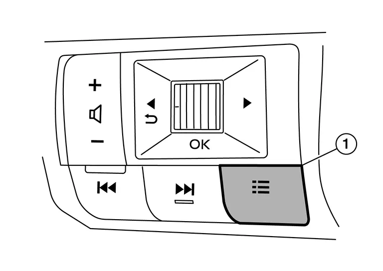
While pressing the control switch (1), place ignition switch ON.
-
Keep pressing the control switch for 1 seconds or more.
-
Press the control switch at least 3 times. (Within 7 seconds after the ignition switch is turned ON.)
-
“Work instruction code” is indicated in the top portion of information display and self-diagnosis is started.
 NOTE:
NOTE: When on-board diagnosis does not start, check the following items and replace combination meter if the check results are normal.
-
Combination meter power supply and ground circuits. Refer to Diagnosis Procedure.
-
Steering switch signal circuits. Refer to Component Function Check.
-
-
The mode switches in the order shown below each time the control switch is pressed.
 NOTE:
NOTE: -
If the control switch is not operated for 20 seconds or more, the self-diagnosis mode is automatically cancelled.
-
The self-diagnosis mode is cancelled by turning the key switch OFF.
-
The self-diagnosis mode is cancelled by engine speed 170 rpm or more.
-
| Test order | Test item | Description | |
|---|---|---|---|
| 1 | Work instruction code | This item is displayed, but not used. | |
| 2 | Spare parts No. | ||
| Soft ware code | |||
| Flash rom No. | |||
| 3 | EEPROM code | ||
| 4 | Hardware code | ||
| 5 | PCB code | ||
| 6 | Circuit check |
The pointer of the following items moves from 0 to MAX then from MAX to 0.
If any one of the pointers does not sweep, replace combination meter.
|
|
| 7 – 10 | Color check | Performs the color check of the information display. | |
| 11 | Error code* |
Displays the error code of the following items.
|
|
| 12 | Warning/indicator lamp check |
All warning/indicator lamp illuminate. Security indicator lamp are not illuminate.
|
|
 NOTE:
NOTE:  NOTE:
NOTE:  NOTE:
NOTE:
When the control switch is pressed during the indication of "Test order 12", test item returns to "Test order 2".
*: Error Code
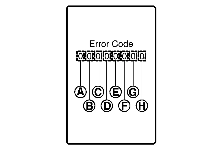
| Item | Code | Description | Action to take/Reference | |
|---|---|---|---|---|
 |
Speedometer | 0 | Normal | — |
| 1 | A Nissan Pathfinder vehicle speed signal can not be received from ECM. |
Select “Self Diagnostic Result” of “ENGINE.” Refer to DTC Index. |
||
| 2 | A Nissan Pathfinder vehicle speed signal received from ECM is abnormal. (FFFFh) | |||
 |
Tachometer | 0 | Normal | — |
| 1 | An engine speed signal cannot be received from ECM. |
Select “Self Diagnostic Result” of “ENGINE.” Refer to DTC Index. |
||
 |
Fuel gauge | 0 | Normal | — |
| 1 | Fuel gauge circuit is short. | Refer to Diagnosis Procedure. | ||
| 2 | Fuel gauge circuit is open. | |||
 |
Engine coolant temperature gauge | 0 | Normal | — |
| 1 | An engine coolant temperature signal cannot be received from ECM. |
Select “Self Diagnostic Result” of “ENGINE.” Refer to DTC Index. |
||
 |
|
0 | Normal | — |
| 1 | When judging that the illumination control switch signal circuit is short-circuited for 5 minutes or more. | Refer to Diagnosis Procedure. | ||
| 2 | When judging that the steering switch (control switch) signal circuit is short-circuited for 5 minutes or more. | Refer to Component Function Check. | ||
| 3 | When judging that the illumination control switch and steering switch (control switch) signal circuit are short-circuited for 5 minutes or more. | Refer to Diagnosis Procedure and Component Function Check. | ||
 |
— | 0 | Displays “0” constantly. | — |
 |
— | 0 | Displays “0” constantly. | — |
 |
— | 0 | Displays “0” constantly. | — |
CONSULT Function (METER/M&A)
APPLICATION ITEMS
CONSULT can perform the following diagnosis modes via CAN communication and the combination meter.
| Diagnosis mode | Description |
|---|---|
| Self Diagnostic Result | Display non-network DTC which combination meter memorizes. |
| Data Monitor | Displays combination meter input/output data in real time. |
| ECU Identification | Displays combination meter part number. |
| Warning History | Lighting history of the warning lamp and indicator lamp can be checked. |
| Network-DTC | Display network DTC which combination meter memorizes when performing "Diagnosis (All System)". |
| CAN Diag Support Monitor* |
The mode is indicated, but not monitored.
|
 NOTE:
NOTE: *: Displays when performing "Diagnosis (All System)".
SELF DIAG RESULT
Refer to DTC Index.
Freeze frame data (FFD)
When DTC is detected, the following vehicle condition is recorded and it is displayed on the CONSULT screen.
| Item name | Display item | |
|---|---|---|
| ODO/TRIP METER |
Records an odometer value when DTC is detected.
|
|
| DTC count | Records the number of times DTC was detected. | |
DATA MONITOR
 NOTE:
NOTE:
The following table includes information (items) inapplicable to this Nissan Pathfinder vehicle. For information (items) applicable to this vehicle, refer to CONSULT display items.
Display Item List
X: Applicable
| Display item [Unit] |
MAIN SIGNALS |
Description |
|---|---|---|
|
SPEED METER [mph or km/h] |
X |
Value of Nissan Pathfinder vehicle speed signal received from ECM via CAN communication. 655.35 is displayed when the malfunction signal is received.
|
|
SPEED OUTPUT [mph or km/h] |
X |
Nissan Pathfinder Vehicle speed signal value transmitted to other units via CAN communication. 655.35 is displayed when the malfunction signal is received.
|
|
ODO OUTPUT [km/h] |
Odometer signal received from ABS actuator and electric unit (control unit) via CAN communication. | |
|
TACHO METER [rpm] |
X |
Value of the engine speed signal received from ECM via CAN communication. 8191.875 is displayed when the malfunction signal is received.
|
|
FUEL METER [L] |
X | Fuel level indicated on combination meter. |
|
W TEMP METER [°F or °C] |
X |
Value of engine coolant temperature signal is received from ECM via CAN communication. 215 is displayed when the malfunction signal is input.
|
|
ABS W/L [On/Off] |
Status of ABS warning lamp detected from ABS warning lamp signal is received from ABS actuator and electric unit (control unit) via CAN communication. | |
|
VDC/TCS IND [On/Off] |
Status of VDC OFF indicator lamp detected from VDC OFF indicator lamp signal is received from ABS actuator and electric unit (control unit) via CAN communication. | |
|
SLIP IND [On/Off] |
Status of VDC warning lamp detected from VDC warning lamp signal received from ABS actuator and electric unit (control unit) via CAN communication. | |
|
BRAKE W/L [On/Off] |
Status of brake warning lamp detected from brake warning lamp signal is received from ABS actuator and electric unit (control unit) via CAN communication and brake fluid level switch signal from brake fluid level switch. Displays “Off” if the brake warning lamp is illuminated when the valve check starts, the parking brake switch is turned ON or the brake fluid level switch is turned ON.
|
|
|
E-PKB warning lamp [On/Off] |
Status of electric parking brake warning lamp detected from electric parking brake warning lamp signal from electric parking brake control module via CAN communication. | |
|
HI-BEAM IND [On/Off] |
Status of high beam indicator lamp detected from high beam status signal is received from BCM via CAN communication. | |
|
TURN IND [On/Off] |
Status of turn signal indicator lamp detected from turn indicator signal is received from BCM via CAN communication. | |
|
FR FOG IND [On/Off] |
Status of front fog lamp indicator lamp detected from front fog light status signal is received from BCM via CAN communication. | |
|
RR FOG IND [Off] |
This item is displayed, but cannot be monitored.
|
|
|
LIGHT IND [On/Off] |
Status of position lamp indicator lamp detected from position light status signal is received from BCM via CAN communication. | |
|
OIL W/L [On/Off] |
Status of engine oil pressure warning detected from engine oil pressure warning lamp signal is received from ECM via CAN communication. | |
|
MIL [On/Off] |
Status of malfunction indicator lamp detected from malfunctioning indicator lamp signal is received from ECM via CAN communication. | |
|
BA W/L [On/Off] |
Status of AEB warning lamp judged from AEB warning lamp signal received from ADAS control unit 2 via CAN communication. | |
|
WASHER W/L [On/Off] |
Status of low washer fluid warning judged from washer level switch input to combination meter. | |
|
AIR PRES W/L [On/Off] |
Status of low tire pressure warning lamp judged from low tire pressure lamp signal received from BCM via CAN communication. | |
|
EPS W/L [On/Off] |
Status of electric power steering warning lamp detected from electric power steering warning lamp signal is received from EPS control unit via CAN communication. | |
|
DDS W/L [Off] |
This item is displayed, but cannot be monitored.
|
|
|
CHAGE W/L [On/Off] |
Status of 12V battery charge warning lamp judged from battery warning request signal received from ECM or IPDM E/R via CAN communication. | |
|
E-PKB indicator [On/Off] |
Status of electric parking brake indicator lamp detected from electric parking brake indicator lamp signal from electric parking brake control module via CAN communication. | |
|
BRAKE OIL SW [On/Off] |
Status of brake fluid level switch. | |
|
PASS BUCKLE SW [On/Off] |
Status of front seat belt buckle switch (passenger side) detected from passenger seat belt buckle switch signal from air bag diagnosis sensor unit via CAN communication. | |
|
CHG CONCT DET [Off] |
This item is displayed, but cannot be monitored.
|
|
|
DISTANCE [km] |
Value of distance to empty calculated by combination meter. | |
|
OUTSIDE TEMP [°F or °C] |
Ambient temperature value converted from ambient sensor signal received from ambient sensor. This may not match with the temperature value indicated on the information display. (Because the information display value is a corrected value from the ambient sensor input value.)
|
|
|
BUZZER [On/Off] |
X | Buzzer status (in the combination meter) is detected from the buzzer output signal received from each unit via CAN communication and the warning output condition of the combination meter. |
|
STRG SW INPUT [SW1-SW12, NOT INPUT] |
Status of steering switch. | |
|
HI-BEAM ASST IND [On/Off] |
Status of high beam assist indicator lamp from high beam assist indicator lamp signal is received from BCM via CAN communication. | |
|
DIPPED BEAM IND [Off] |
This item is displayed, but cannot be monitored.
|
|
| Engine Off timer |
This item is displayed, but cannot be monitored.
|
|
| Nissan Pathfinder Vehicle distance |
This item is displayed, but cannot be monitored.
|
|
|
EAPM status [No spprt] |
|
This item is displayed, but cannot be monitored.
|
 NOTE:
NOTE:  NOTE:
NOTE:  NOTE:
NOTE:  NOTE:
NOTE:  NOTE:
NOTE:  NOTE:
NOTE:  NOTE:
NOTE:  NOTE:
NOTE:  NOTE:
NOTE:  NOTE:
NOTE:  NOTE:
NOTE:  NOTE:
NOTE:  NOTE:
NOTE: ECU IDENTIFICATION
The combination meter part number is displayed.
WARNING HISTORY
-
Stores histories when warning/indicator lamp is turned on.
-
“WARNING HISTORY” indicates the “TIME” when the warning/ indicator lamp is turned on.
-
The “TIME” above is:
-
0: The condition that the warning/indicator lamp has been turned on 1 or more times after starting the engine and waiting for 30 seconds.
-
1 - 39: The number of times the engine was restarted after the 0 condition.
-
NO WARNING HISTORY: Stores NO (0) turning on history of warning/indicator lamp.
-
 NOTE:
NOTE:
-
WARNING HISTORY is not stored for approximately 30 seconds after the engine starts.
-
Brake warning lamp does not store any history when the parking brake is applied or the brake fluid level gets low.
Display Item
| Display item | Description |
|---|---|
| ABS W/L | Lighting history of ABS warning lamp. |
| VDC/TCS IND | Lighting history of VDC OFF indicator lamp. |
| SLIP IND | Lighting history of VDC warning lamp. |
| BRAKE W/L | Lighting history of brake warning lamp. |
| OIL W/L | Lighting history of engine oil pressure warning lamp. |
| C-ENG W/L | Lighting history of malfunction indicator lamp (MIL). |
| BA W/L | Lighting history of AEB warning lamp. |
| AIR PRES W/L | Lighting history of low tire pressure warning lamp. |
| EPS W/L | Lighting history of electric power steering warning lamp. |
| CHAGE W/L | Lighting history of 12V battery charge warning lamp. |
 NOTE:
NOTE:
In items displayed on the CONSULT screen, only those listed in the above table are used.

Nissan Pathfinder (R53) 2022-2026 Service Manual
Contact Us
Nissan Pathfinder Info Center
Email: info@nipathfinder.com
Phone: +1 (800) 123-4567
Address: 123 Pathfinder Blvd, Nashville, TN 37214, USA
Working Hours: Mon–Fri, 9:00 AM – 5:00 PM (EST)
