Nissan Pathfinder: System Description - Component Parts ++
Meter System
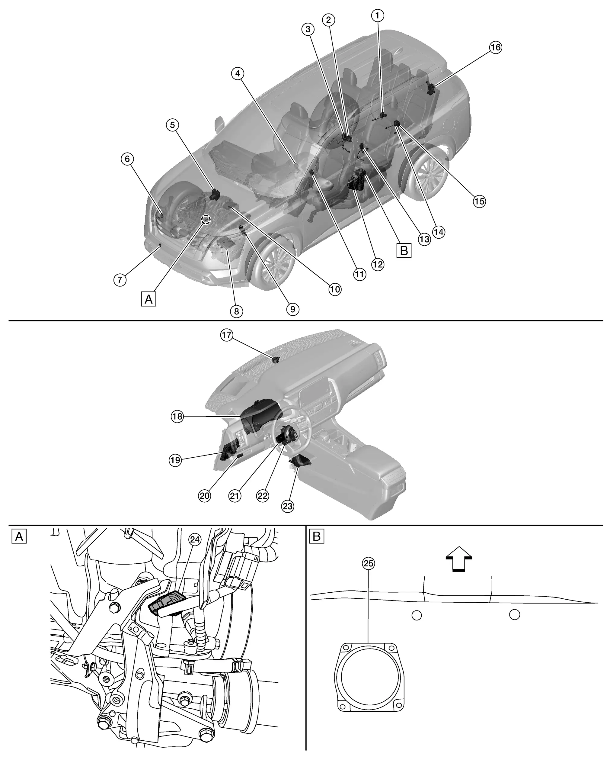
Component Parts Location
 |
Nissan Pathfinder Vehicle front | ||
| A. | View with engine assembly removed | B. | View of the fuel pump and fuel level sensor inspection hole cover with the 2nd row seat removed |
| No. | Component | Function |
|---|---|---|
| 1. | 3rd row seat belt buckle switch RH | Transmits the 3rd row seat belt buckle switch RH signal to the air bag diagnosis sensor unit. |
| 2. | 2nd row seat belt buckle switch CTR (if equipped) | Transmits the 2nd row seat belt buckle switch CTR signal to the air bag diagnosis sensor unit. |
| 3. | 2nd row seat belt buckle switch RH | Transmits the 2nd row seat belt buckle switch RH signal to the air bag diagnosis sensor unit. |
| 4. | Front seat belt buckle switch RH | Transmits the front seat belt buckle switch RH signal to the air bag diagnosis sensor unit. |
| 5. | ABS (Anti-lock Braking System) actuator and electric unit (control unit) |
Transmits the Nissan Pathfinder vehicle speed signal to the combination meter via CAN communication. Refer to Component Parts Location for detailed component location. |
| 6. | Washer fluid level switch | Transmits the washer fluid level switch signal to the combination meter. |
| 7. | Ambient sensor | Transmits the ambient sensor signal to the combination meter. |
| 8. | ECM (Engine Control Module) |
Transmits each signal to the combination meter via CAN communication. Refer to System Description. Refer to Component Parts Location for detailed component location. |
| 9. | TCM (Transmission Control Module) |
Transmits each signal to the combination meter via CAN communication. Refer to System Description. Refer to Component Parts Location for detailed component location. |
| 10. | Brake fluid level switch | Transmits the brake fluid level switch signal to the combination meter. |
| 11. | Front seat belt buckle switch LH | Transmits the front seat belt buckle switch LH signal to the BCM. |
| 12. | Front door lock assembly LH (door switch) shown others similar | Transmits front door switch LH signal to the BCM. |
| 13. | 2nd row seat belt buckle switch LH | Transmits the 2nd row seat belt buckle switch LH signal to the air bag diagnosis sensor unit. |
| 14. | 3rd row seat belt buckle switch CTR | Transmits the 3rd row seat belt buckle switch CTR signal to the air bag diagnosis sensor unit. |
| 15. | 3rd row seat belt buckle switch LH | Transmits the 3rd row seat belt buckle switch LH signal to the air bag diagnosis sensor unit. |
| 16. | Back door lock assembly (ajar switch) | Transmits the back door ajar switch signal to the BCM. |
| 17. | Master speaker | Refer to Master Speaker. |
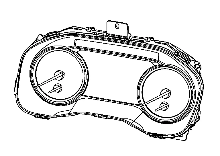
| 18. | Combination meter | Refer to Combination Meter. |
| 19. | BCM (Body Control Module) |
Based on the signals received from various units and switches, transmits the buzzer output signal to the combination meter via CAN communication. Refer to Component Part Location for detailed component location. |
| 20. | Illumination control switch | Refer to Illumination Control Switch. |
| 21. | Steering switches | Refer to Steering Switches. |
| 22. | Combination switch (spiral cable) | Provides a pass-through for the steering switch signal from the steering switches to the combination meter. |
| 23. | Air bag diagnosis sensor unit |
Transmits the following seat belt buckle switch signals to the combination meter via CAN communication:
|
| 24. | Engine oil pressure sensor | Transmits the engine oil pressure sensor signal to the ECM. |
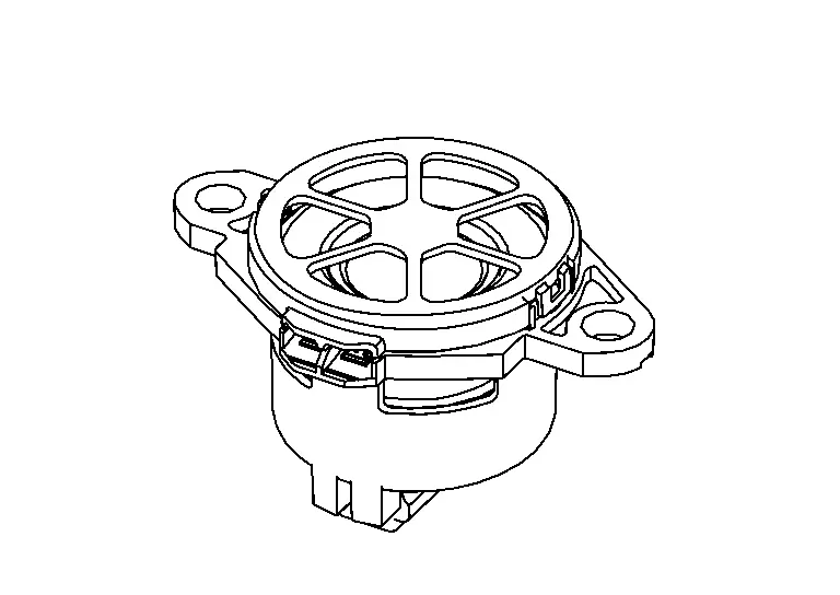
| 25. | Fuel level sensor unit and fuel pump (fuel level sensor) | Transmits the fuel level sensor signal to the combination meter. |
Design
ARRANGEMENT OF COMBINATION METER
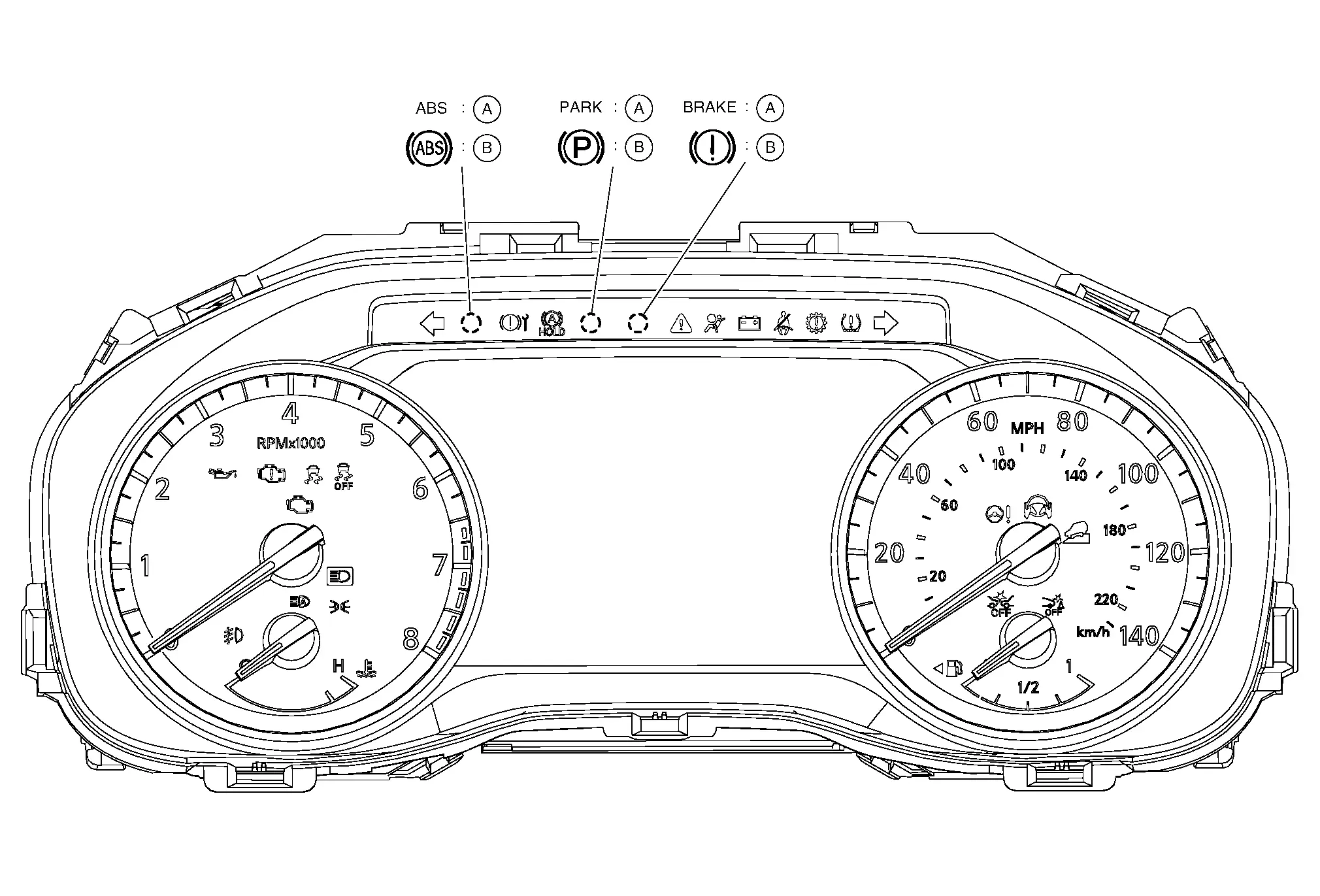
| A. | USA. | B. | Except USA |
Combination Meter
The combination meter controls the following items according to the signals received from each unit via CAN communication and the signals from switches and sensors.
-
Measuring instruments
-
Speedometer
-
Tachometer
-
Engine coolant temperature gauge
-
Fuel gauge
-
-
Indicator lamps
-
Warning lamps
-
Meter illumination control
-
Meter effect function
-
Information display
CLOCK SPECIFICATIONS
| Operating voltage | (V) | 11 - 16 |
| Accuracy | (sec./day) | Approx. ± 6 |
 NOTE:
NOTE:
The time is displayed on the information display. When a time lag of more than the above described accuracy occurs, the combination meter battery power supply voltage may be low. In this case, check 12 V battery for malfunction causing low power supply voltage. Models with the navigation system are free of time lag resulted from low power supply voltage because of the synchronization with GPS signals.
Master Speaker
-
The master speaker is installed in the top center of the instrument panel assembly.
-
The master speaker sounds with the signal from the combination meter.
Steering Switch
-
The steering switches are located on the steering wheel.
-
Transmits the steering switch signal to the combination meter.
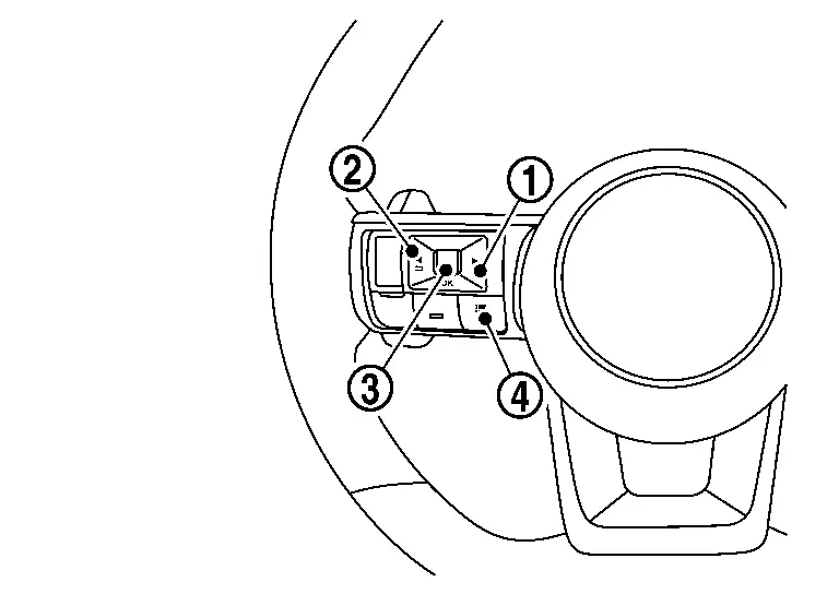
| No. | Switch name | Operation | Description | |
|---|---|---|---|---|
| 1. | RIGHT switch | Press | Switches the screen shown on the information display. | |
| 2. | LEFT/BACK switch | Press |
|
|
| 3. | OK switch | Press | Switches the screen shown on the information display. | |
| Scroll dial | Up |
|
||
| Down |
|
|||
| 4. | Control switch | Press | Switches the screen shown on the information display to the short cut menu screen. | |
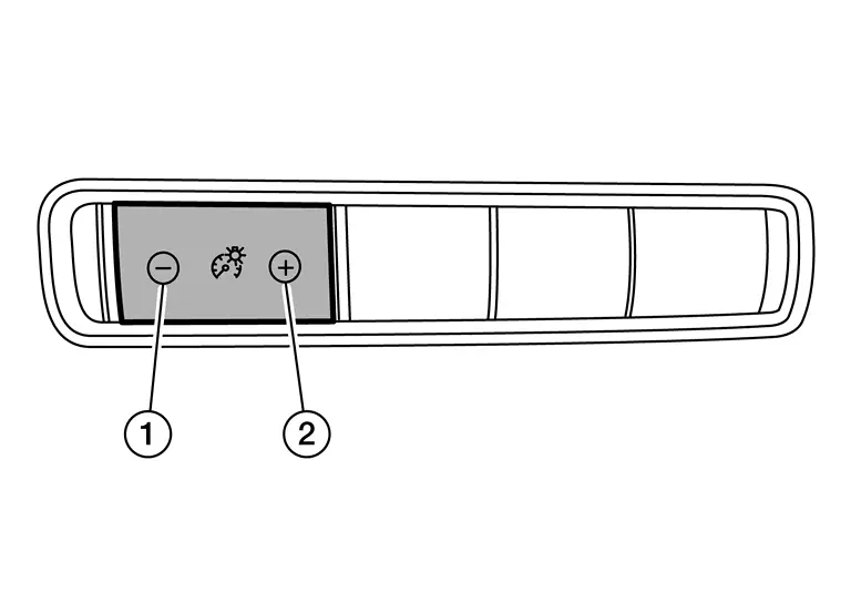
Illumination Control Switch
-
The illumination control switch is located on the instrument lower panel LH.
-
Transmits the following signals to the combination meter:
-
Illumination control switch signal (+)
-
Illumination control switch signal (−)
-
| No. | Switch name | Operation | Description |
|---|---|---|---|
| 1. | Illumination control switch (−) | Press | The brightness of the combination meter and information display can be adjusted. |
| 2. | Illumination control switch (+) |
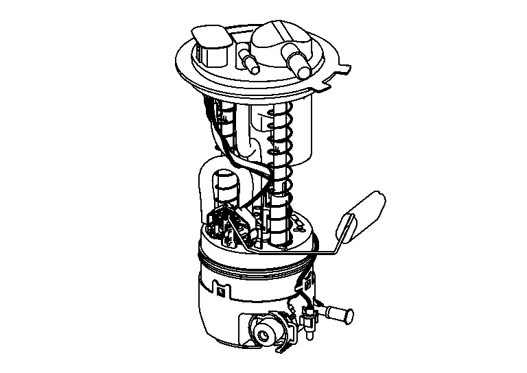
Fuel Level Sensor Unit And Fuel Pump (Fuel Level Sensor)
-
Fuel level sensor unit and fuel pump (fuel level sensor) is located in the fuel tank.
-
Transmits the fuel level sensor signal to the combination meter.
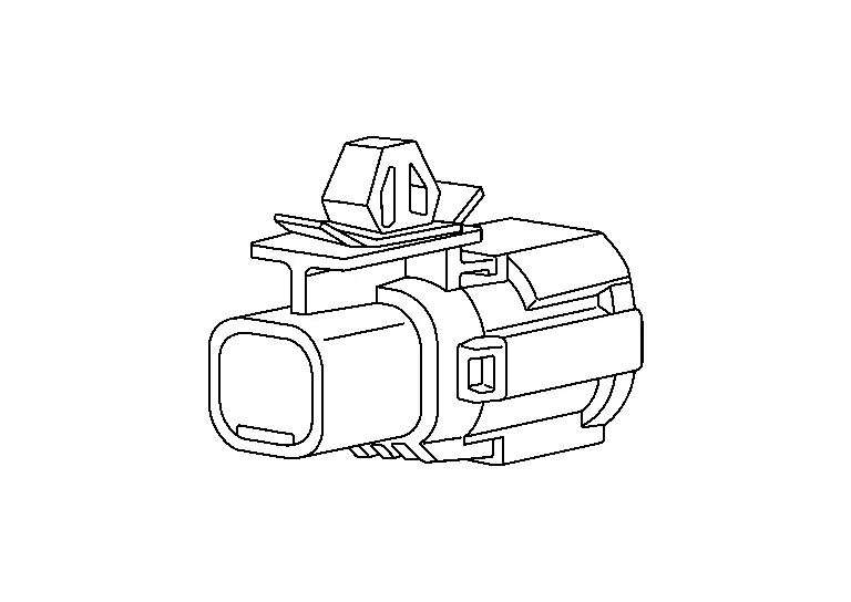
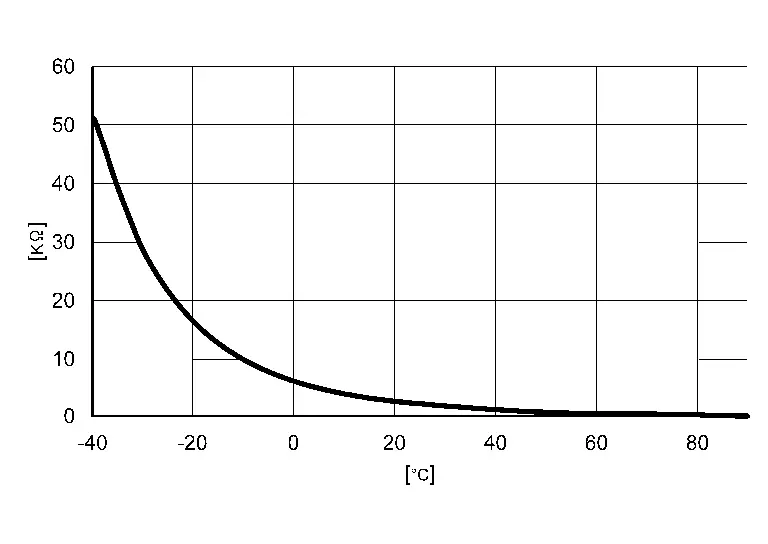
Ambient Sensor
-
The ambient sensor is attached to the active grille shutter.
-
Ambient sensor measures ambient air temperature.
-
Ambient sensor transmits the ambient sensor signal to the combination meter.
-
Ambient sensor uses a thermistor which is sensitive to the change in temperature. The electrical resistance of the thermistor decreases as temperature increases.
Head up Display
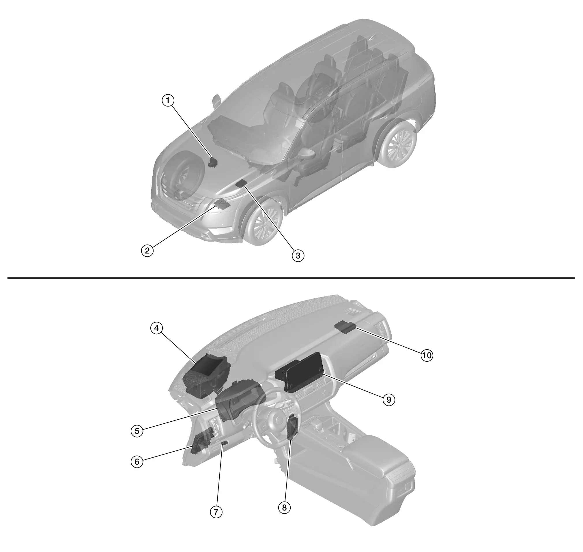
Component Parts Location
| No. | Component | Function |
|---|---|---|
| 1. | ABS (Anti-lock Braking System) actuator and electric unit (control unit) |
Transmits the odometer signal to the Head Up Display unit via CAN communication. Refer to Component Parts Location for detailed component location. |
| 2. | ECM (Engine Control Module) |
Transmits the ASCD status to the Head Up Display unit via CAN communication. Refer to Component Parts Location for detailed component location. |
| 3. | IPDM E/R (Intelligent Power Distribution Module Engine Room) |
Transmits the battery voltage signal to the Head Up Display unit via CAN communication. Refer to Component Parts Location for detailed component location. |
| 4. | Head Up Display unit | Refer to Head Up Display Unit. |
| 5. | Combination meter |
Transmits the following signals and HUD setting signal to the Head Up Display unit via CAN communication:
|
| 6. | BCM (Body Control Module) |
Transmits the following signals to the Head Up Display unit via CAN communication:
|
| 7. | Head Up Display switch | Refer to Head Up Display Switch. |
| 8. | ADAS (Advanced Driver Assistance System) control unit 2 |
Transmits the display signal of the driver assistance and warning to the Head up Display unit via CAN communication. Refer to Component Parts Location for detailed component location. |
| 9. | AV control unit |
Transmits the key link activation status signal to the Head Up Display unit via CAN communication. Refer to Component Parts Location for detailed component location. |
| 10. | Intelligent Key unit |
Transmits the user identification signal to the Head Up Display unit via CAN communication. Refer to Component Parts Location for detailed component location. |
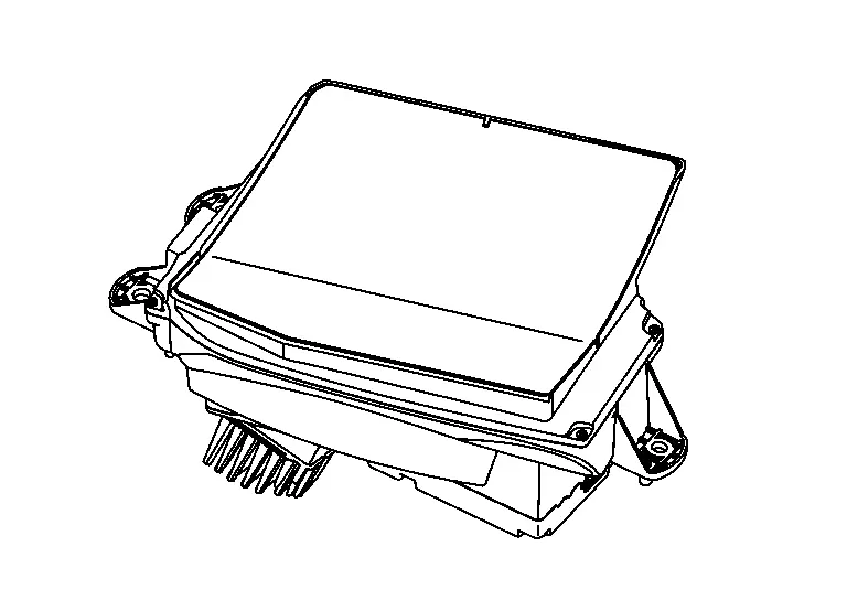
Head Up Display Unit
-
The head up display unit is installed in the top left side of the instrument panel.
-
Necessary signals are transmitted/received to/from control unit via AV and CAN communication.
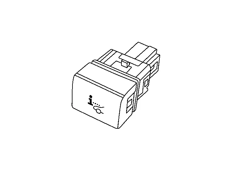
Head Up Display Switch
-
The head up display switch is located in the instrument panel lower LH.
-
The head up display switch is used to turn the system ON/OFF.

Nissan Pathfinder (R53) 2022-2026 Service Manual
Contact Us
Nissan Pathfinder Info Center
Email: info@nipathfinder.com
Phone: +1 (800) 123-4567
Address: 123 Pathfinder Blvd, Nashville, TN 37214, USA
Working Hours: Mon–Fri, 9:00 AM – 5:00 PM (EST)
