Nissan Pathfinder: System Description - Component Parts ++
Exterior Lighting System
Component Parts Location
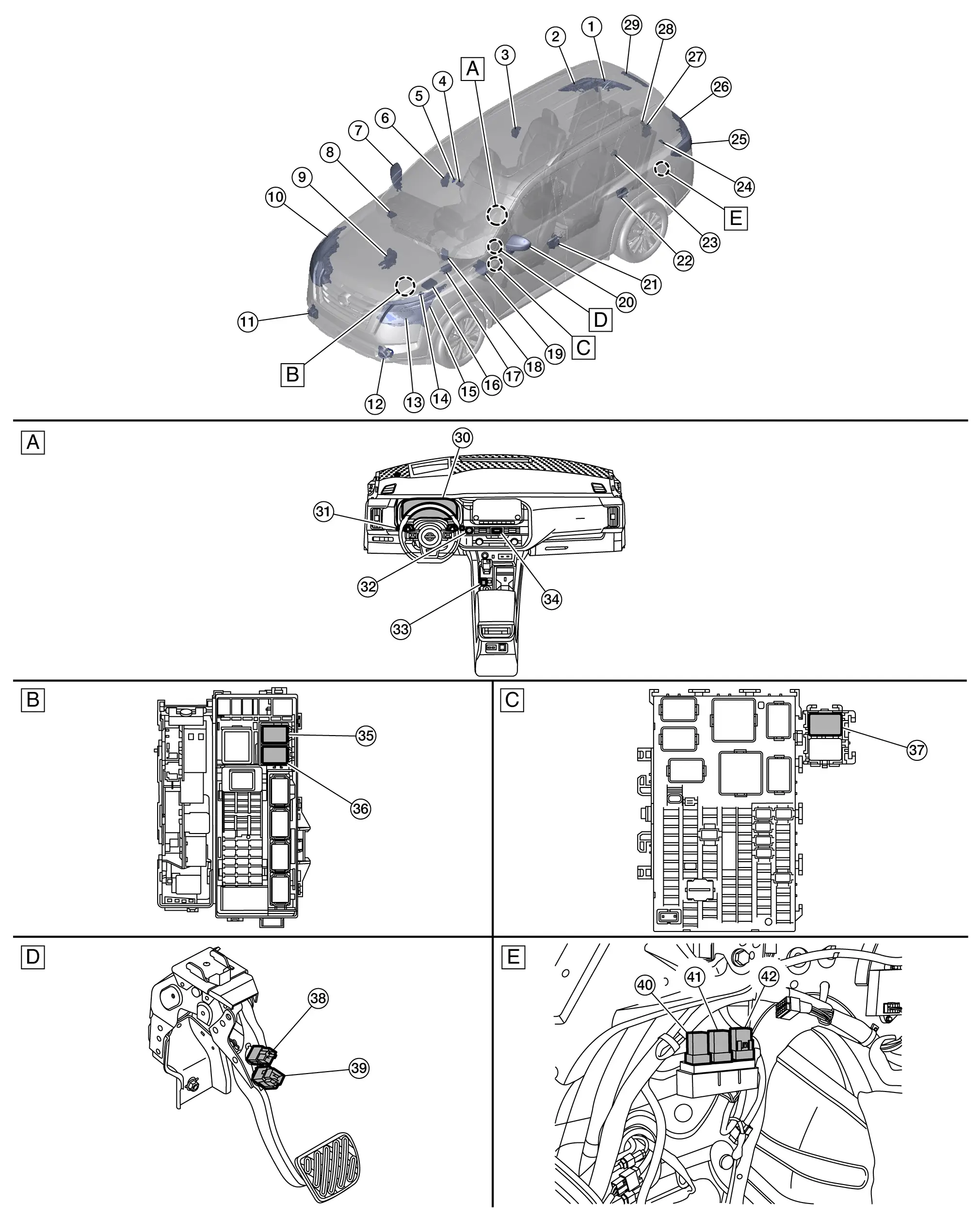
| A. | Instrument panel assembly | B. | Fuse, fusible link and relay box (view with fuse, fusible link and relay box removed) | C. |
Fuse block (J/B) [view with fuse block (J/B)] removed] (with heated steering wheel shown, without heated steering wheel similar) |
| D. | Brake pedal assembly (view with brake pedal assembly removed) | E. | Left rear of Nissan Pathfinder vehicle (view with finisher removed) | ||
| No. | Component | Function | |
|---|---|---|---|
| 1. | Rear combination lamp RH (back door side) | Tail lamp | Refer to Bulb Specifications. |
| Back-up lamp | |||
| 2. | Rear combination lamp RH (body side) | Stop lamp | Refer to Bulb Specifications. |
| Tail lamp | |||
| Side marker | |||
| Rear turn signal lamp | |||
| 3. | Rear door lock assembly RH (door switch) |
Transmits the door switch signal to the BCM. Refer to Door Lock Assembly for detailed component location. |
|
| 4. | Front camera unit (if so equipped) |
Front camera unit detects a Nissan Pathfinder vehicle ahead or when an oncoming vehicle appears to operate the high beam assist (HBA) system. Refer to Front Camera Unit for detailed component location. |
|
| 5. | Rain sensor | Refer to Rain Sensor. | |
| 6. | Front door lock assembly RH (door switch) |
Transmits the door switch signal to the BCM. Refer to Door Lock Assembly for detailed component location. |
|
| 7. | Door mirror RH | Side turn signal lamp (if so equipped) | Refer to Bulb Specifications. |
| 8. | Intelligent Key unit |
Transmits the door lock/unlock request signal via CAN communication. Refer to Intelligent Key unit for detailed component location. |
|
| 9. | ABS (Anti-locking Braking System) actuator and electric unit (control unit) |
Transmits the Nissan Pathfinder vehicle speed signal and parking brake status signal via CAN communication. Refer to ABS Actuator and Electric Unit (Control Unit) for detailed component location. |
|
| 10. | Front combination lamp RH | Headlamp (High beam) | Refer to Bulb Specifications. |
| Headlamp (Low beam) | |||
| Parking lamp/daytime running light | |||
| Turn signal lamp | |||
| Side marker lamp | |||
| LED headlamp control module | Refer to LED Headlamp Control Module. | ||
| 11. | Front fog lamp RH | Refer to Bulb Specifications. | |
| 12. | Front fog lamp LH | Refer to Bulb Specifications. | |
| 13. | ECM (Engine Control Module) |
Transmits the engine status signal via CAN communication. Refer to ECM for detailed component location. |
|
| 14. | TCM (Transmission Control Module) |
Transmits the shift position signal via CAN communication. Refer to TCM for detailed component location. |
|
| 15. | Front combination lamp LH | Headlamp (High beam) | Refer to Bulb Specifications. |
| Headlamp (Low beam) | |||
| Parking lamp/daytime running light | |||
| Turn signal lamp | |||
| Side marker lamp | |||
| LED headlamp control module | Refer to LED Headlamp Control Module. | ||
| 16. | IPDM E/R (Intelligent Power Distribution Module Engine Room) |
IPDM E/R Smart FET (field-effect transistor) supplies voltage to the loads according to the request from the BCM via CAN communication. Refer to System Description. |
|
| 17. | Air bag diagnosis sensor unit |
Transmits the car crash information signal to the BCM via CAN communication for the auto hazard function. Refer to Air Bag Diagnosis Sensor Unit for detailed component location. |
|
| 18. | ADAS (Advanced Driver Assistance System) control unit 2 |
Transmits the stop lamp request signal to the BCM via CAN communication for the AEB (automatic emergency braking) function. Refer to ADAS Control Unit 2 for detailed component location. |
|
| 19. | BCM (Body Control Module) |
|
|
| 20. | Door mirror LH | Side turn signal lamp (if so equipped) | Refer to Bulb Specifications. |
| 21. | Front door lock assembly LH (door switch) |
Transmits the door switch signal to the BCM. Refer to Door Lock Assembly for detailed component location. |
|
| 22. | Rear door lock assembly LH (door switch) |
Transmits the door switch signal to the BCM. Refer to Door Lock Assembly for detailed component location. |
|
| 23. | Trailer receptacle (if so equipped) | Allows for the use of trailer lamps when a trailer is connected to the trailer receptacle. | |
| 24. | License plate lamp LH | Refer to Bulb Specifications. | |
| 25. | Rear combination lamp LH (body side) | Stop lamp | Refer to Bulb Specifications. |
| Tail lamp | |||
| Side marker | |||
| Rear turn signal lamp | |||
| 26. | Rear combination lamp RH (back door side) | Tail lamp | Refer to Bulb Specifications. |
| Back-up lamp | |||
| 27. | Back door lock assembly (ajar switch) |
Transmits the ajar switch signal to the BCM to operate the autolight system. Refer to Back Door Lock Assembly for detailed component location. |
|
| 28. | License plate lamp RH | Refer to Bulb Specifications. | |
| 29. | High-mounted stop lamp | Refer to Bulb Specifications. | |
| 30. | Combination meter |
|
|
| 31. | Combination switch (lighting and turn signal switch) |
Transmits the status of the combination switch (lighting and turn signal switch) to the BCM. Refer to Lighting and Turn Signal Switch. |
|
| 32. | Push-button ignition switch |
|
|
| 33. | Parking brake switch |
Transmits the parking brake switch signal to the ABS actuator and electric unit (control unit). Refer to Parking Brake Switch for detailed component location. |
|
| 34. | Hazard switch | Refer to Hazard Switch. | |
| 35. | Trailer turn relay LH (if so equipped) |
|
|
| 36. | Trailer turn relay RH (if so equipped) |
|
|
| 37. | Back-up lamp relay |
|
|
| 38. | Brake pedal position switch | Refer to Brake Pedal Position Switch. | |
| 39. | Stop lamp switch | Refer to Stop Lamp Switch. | |
| 40. | Trailer tow relay-1 (if so equipped) | Trailer tow relay-1 is controlled by the BCM. | |
| 41. | Trailer back-up relay (if so equipped) |
|
|
| 42. | Trailer tow relay-2 (if so equipped) | Trailer tow relay-2 is controlled by the BCM. | |
LED Headlamp Control Module
-
LED headlamp control module integrated to the headlamp.
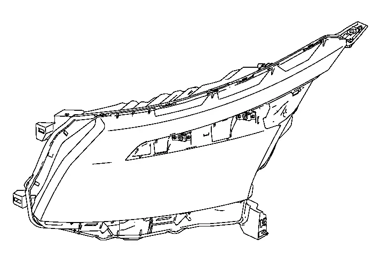
(Front combination lamp LH shown, RH similar)
-
When power is supplied from the battery and the LED headlamp control module receives the control signal from the IPDM E/R, the LED headlamp control module internally calculates the supplied power. The calculated power is distributed to multiple LEDs that consist of circuit boards and other components, illuminating each lamp.
-
When a malfunction is detected in the headlamp (LO) circuit, the LED headlamp control module outputs a headlamp warning signal to the IPDM E/R via LIN communication to inform the driver of the malfunction.
-
The IPDM E/R transmits the control signal and the request via LIN communication to the LED headlamp control module, and turns each lamp ON.
-
The LED headlamp control module transmits the headlamp warning signal to the IPDM E/R via LIN communication according to the headlamp (LO) circuit malfunction condition.
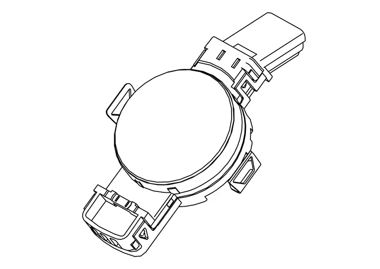
Rain Sensor
-
The rain sensor is installed on the windshield.
-
The rain sensor transmits the light sensor signal to the BCM via LIN communication according to the brightness of ambient light.
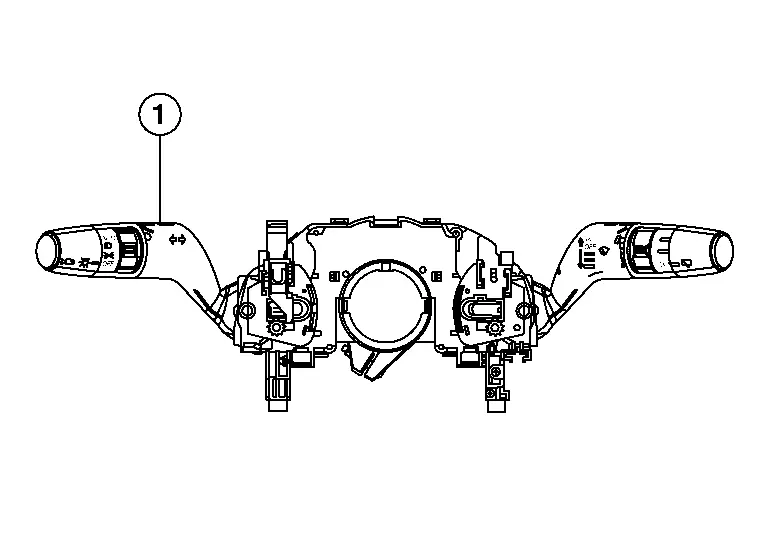
Lighting and Turn Signal Switch
-
Lighting and turn signal switch (1) is integrated with the combination switch.
-
Transmits the status of the lighting and turn signal switch to the BCM with the combination switch reading function.
Hazard Switch
-
Hazard switch is installed in the center ventilator finisher.
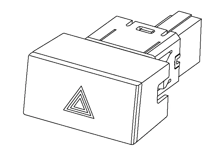
-
Transmits the ON/OFF status of the hazard switch to the BCM, flashing the hazard warning lamp.
Stop Lamp Switch
-
Stop lamp switch is installed on the brake pedal assembly.
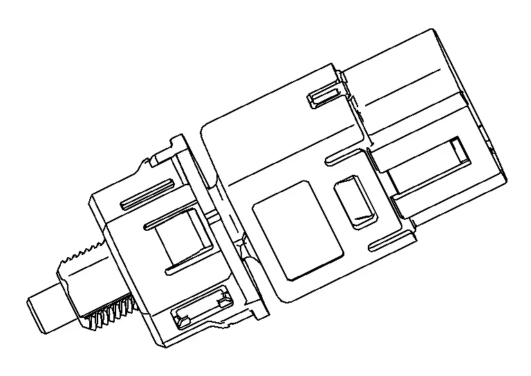
-
The BCM detects the ON/OFF status of the stop lamp switch and illuminates the stop lamp.
Brake Pedal Position Switch
-
Brake pedal position switch is installed on the brake pedal assembly.
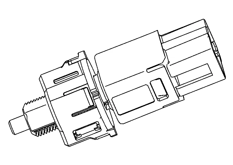
-
The BCM detects the ON/OFF status of the brake pedal position switch and illuminates the stop lamp.

Nissan Pathfinder (R53) 2022-2026 Service Manual
Contact Us
Nissan Pathfinder Info Center
Email: info@nipathfinder.com
Phone: +1 (800) 123-4567
Address: 123 Pathfinder Blvd, Nashville, TN 37214, USA
Working Hours: Mon–Fri, 9:00 AM – 5:00 PM (EST)
