Nissan Pathfinder: Transaxle & Transmission - Basic Inspection
- Diagnosis and Repair Work Flow
- Additional Service When Replacing Tcm
- Additional Service When Replacing Transaxle Assembly
- Additional Service When Replacing Control Valve
- Dog Clutch Position Sensor Calibration
- Learning of Solenoid Characteristic
- A/t Clutch Touch Point Learning
- Mac Key Writing
- A/t Fluid Cooler System
- A/t Position
- How to Erase Permanent Dtc
Diagnosis and Repair Work Flow Nissan Pathfinder R53
Work Flow
OBTAIN INFORMATION ABOUT SYMPTOM
Refer to Diagnostic Work Sheet and interview the customer to obtain the malfunction information (conditions and environment when the malfunction occurred) as much as possible when the customer brings in the Nissan Pathfinder vehicle.
>>
GO TO 2.
CHECK DTC
-
Before checking the malfunction, check whether any DTC exists.
-
If DTC exists, perform the following operations.
-
Record the DTC and freeze frame data. (Print out the data using CONSULT and affix them to the Work Order Sheet.)
-
Erase DTCs.
-
Check the relationship between the cause that is clarified with DTC and the malfunction information described by the customer. Symptom Table is effective.
-
Do malfunction information and DTC exists?
Malfunction information and DTC exists. >>GO TO 3.
Malfunction information exists, but no DTC. >>GO TO 4.
No malfunction information, but DTC exists.>>GO TO 5.
REPRODUCE MALFUNCTION SYMPTOM
Check any malfunction described by a customer, except those with DTC on the Nissan Pathfinder vehicle.
Also investigate whether the symptom is a fail-safe or normal operation. Refer to Fail-safe.
When a malfunction symptom is reproduced, the question sheet is effective. Refer to Diagnostic Work Sheet.
Verify the relationship between the symptom and the conditions in which the malfunction described by the customer occurs.
>>
GO TO 5.
REPRODUCE MALFUNCTION SYMPTOM
Check the malfunction described by the customer on the Nissan Pathfinder vehicle.
Also investigate whether the symptom is a fail-safe or normal operation. Refer to Fail-safe.
When a malfunction symptom is reproduced, the question sheet is effective. Refer to Diagnostic Work Sheet.
Verify the relationship between the symptom and the conditions in which the malfunction described by the customer occurs.
>>
GO TO 6.
PERFORM “DTC CONFIRMATION PROCEDURE”
Perform “DTC CONFIRMATION PROCEDURE” of the appropriate DTC to check if DTC is detected again.
Refer to DTC Inspection Priority Chart when multiple DTCs are detected, and then determine the order for performing the diagnosis.
 NOTE:
NOTE:
If no DTC is detected, refer to the freeze frame data.
Is any DTC detected?
YES>>GO TO 7.
NO>>Check according to Intermittent Incident.
IDENTIFY MALFUNCTIONING SYSTEM WITH “DIAGNOSIS CHART BY SYMPTOM”
Use Symptom Table from the symptom inspection result in step 4. Then identify where to start performing the diagnosis based on possible causes and symptoms.
>>
GO TO 8.
REPAIR OR REPLACE THE MALFUNCTIONING PARTS
Repair or replace the detected malfunctioning parts.
Reconnect parts or connector after repairing or replacing, and then erase DTC if necessary.
>>
GO TO 8.
FINAL CHECK
Perform “DTC CONFIRMATION PROCEDURE” again to make sure that the repair is correctly performed.
Check that malfunctions are not reproduced when obtaining the malfunction information from the customer, referring to the symptom inspection result in step 3 or 4.
Is DTC or malfunction symptom reproduced?
YES-1>>DTC is reproduced: GO TO 5.
YES-2>>Malfunction symptom is reproduced: GO TO 6.
NO>>Before delivering the Nissan Pathfinder vehicle to the customer, make sure that DTC is erased.
Diagnostic Work Sheet
DESCRIPTION
There are many operating conditions that may cause a malfunction of the transmission parts. By understanding those conditions properly, a quick and exact diagnosis can be achieved.
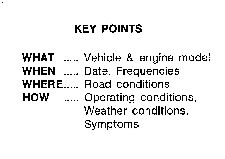
In general, customers have their own criteria for a problem. Therefore, it is important to understand the symptom and status well enough by asking the customer about the concerns carefully. In order to systemize all the information for the diagnosis, prepare the question sheet referring to the question points.
WORKSHEET SAMPLE
| Question Sheet | |||||||
|---|---|---|---|---|---|---|---|
| Customer name MR/MS | Engine # | Manuf. Date | |||||
| Incident Date | VIN | ||||||
| Model & Year | In Service Date | ||||||
| Trans. | Mileage | km/Mile | |||||
| Symptoms | □ Nissan Pathfinder Vehicle does not move (□ Any position □ Particular position ) | ||||||
| □ No upshift (□ 1GR ⇒ 2GR □ 2GR ⇒ 3GR □ 3GR ⇒ 4GR □ 4GR ⇒ 5GR □ 5GR ⇒ 6GR □ 6GR ⇒ 7GR □ 7GR ⇒ 8GR □ 8GR ⇒ 9GR) | |||||||
| □ No downshift (□ 9GR ⇒ 8GR □ 8GR ⇒ 7GR □ 7GR ⇒ 6GR □ 6GR ⇒ 5GR □ 5GR ⇒ 4GR □ 4GR ⇒ 3GR □ 3GR ⇒ 2GR □ 2GR ⇒ 1GR) | |||||||
| □ Lock-up malfunction | |||||||
| □ Shift point too high or too low | |||||||
| □ Shift shock or slip | |||||||
| □ Noise or vibration | |||||||
| □ No kick down | |||||||
| □ No pattern select | |||||||
| □ Others | |||||||
| Frequency | □ All the time | □ Under certain conditions | □ Sometimes ( times a day) | ||||
| Weather conditions | □ Not affected | ||||||
| Weather | □ Fine | □ Clouding | □ Raining | □ Snowing | □ Other ( ) | ||
| Temp. | □ Hot | □ Warm | □ Cool | □ Cold | □ Temp. Approx. °C/°F | ||
| Humidity | □ High | □ Middle | □ Low | ||||
| Transmission conditions | □ Not affected | ||||||
| □ Cold | □ During warm-up | □ After warm-up | |||||
| □ Engine speed ( rpm) | |||||||
| Road conditions | □ Not affected | ||||||
| □ In town | □ In suburbs | □ Freeway | □ Off road (Up/Down) | ||||
| Driving conditions | □ Not affected | ||||||
| □ At starting | □ While idling | □ While engine racing | □ At racing | □ While cruising | |||
| □ While accelerating | □ While decelerating | □ While turning (Right/Left) | |||||
| □ Nissan Pathfinder Vehicle speed [ km/h ( MPH)] | |||||||
| Other conditions | |||||||
Additional Service When Replacing Tcm Nissan Pathfinder 2022
Description
When replacing the TCM, perform the following work. For work procedure, refer to Work Procedure.
WORK AFTER TCM REPLACEMENT
-
TCM programming
 NOTE:
NOTE:
Since vehicle specifications are not yet written in a new TCM, it is necessary to write them with CONSULT.
-
MAC key writing
-
Dog clutch position sensor calibration
-
Learning of solenoid characteristic
-
A/T clutch touch point learning
-
Clear DTC and test drive
Work Procedure
 NOTE:
NOTE:
Before starting, make sure:
-
ASIST on the CONSULT has been synchronized to the current date.
-
All CONSULT software updates (if any) have been installed.
REPLACE TCM
Replace TCM. Refer to Removal and Installation.
>>
GO TO 2.
PERFORM TCM PROGRAMMING
 With CONSULT
Perform TCM programming, according to “Programming” of CONSULT Operation Manual. Refer to CONSULT Operation Manual.
>>
GO TO 3.
WRITE MAC KEY
Perform MAC key writing, Refer to Description.
>>
GO TO 4.
PERFORM DOG CLUTCH POSITION SENSOR CALIBRATION
Perform dog clutch position sensor calibration. Refer to Description.
>>
GO TO 5.
PERFORM LEARNING OF SOLENOID CHARACTERISTIC
Perform learning of solenoid characteristic. Refer to Description.
>>
GO TO 6.
PERFORM A/T CLUTCH TOUCH POINT LEARNING
Perform A/T clutch touch point learning. Refer to Description.
>>
GO TO 7.
CLEAR DTC AND TEST DRIVE
-
Ignition switch OFF and wait for 15 seconds.
-
Ignition switch ON.
-
Clear any DTCs that may have set and then test drive the Nissan Pathfinder vehicle.
>>
WORK END
Additional Service When Replacing Transaxle Assembly Nissan Pathfinder Fifth generation
Description
When replacing the transaxle assembly, perform the following work. For work procedure, refer to Work Procedure.
WORK AFTER A/T ASSEMBLY REPLACEMENT
-
TCM programming
 NOTE:
NOTE:
Since vehicle specifications are not yet written in a new TCM, it is necessary to write them with CONSULT.
-
MAC key writing
-
A/T clutch touch point learning
-
Clear DTC and test drive
Work Procedure
![]() NOTE:
NOTE:
Before starting, make sure:
-
ASIST on the CONSULT has been synchronized to the current date.
-
All CONSULT software updates (if any) have been installed.
REPLACE A/T ASSEMBLY
Replace A/T assembly. Refer to Removal and Installation.
>>
GO TO 2.
PERFORM TCM PROGRAMMING
![]() With CONSULT
With CONSULT
Perform TCM programming, according to “Programming” of CONSULT Operation Manual. Refer to CONSULT Operation Manual.
>>
GO TO 3.
WRITE MAC KEY
Perform MAC key writing, Refer to Description.
>>
GO TO 4.
PERFORM A/T CLUTCH TOUCH POINT LEARNING
Perform A/T clutch learning. Refer to Description.
>>
GO TO 5.
CLEAR DTC AND TEST DRIVE
-
Ignition switch OFF and wait for 15 seconds.
-
Ignition switch ON.
-
Clear any DTCs that may have set and then test drive the Nissan Pathfinder vehicle.
>>
WORK END
Additional Service When Replacing Control Valve Nissan Pathfinder
Description
When replacing the control valve, perform the following work. For work procedure, refer to Work Procedure.
WORK AFTER CONTROL VALVE REPLACEMENT
-
Dog clutch position sensor calibration
-
Learning of solenoid characteristic
-
A/T clutch touch point learning
-
Clear DTC and test drive
Work Procedure
 NOTE:
NOTE:
Before starting, make sure:
-
ASIST on the CONSULT has been synchronized to the current date.
-
All CONSULT software updates (if any) have been installed.
REPLACE CONTROL VALVE
Replace control valve. Refer to Removal and Installation.
>>
GO TO 2.
PERFORM DOG CLUTCH POSITION SENSOR CALIBRATION
Perform dog clutch position sensor calibration. Refer to Description.
>>
GO TO 3.
PERFORM LEARNING OF SOLENOID CHARACTERISTIC
Perform learning of solenoid characteristic. Refer to Description.
>>
GO TO 4.
PERFORM A/T CLUTCH TOUCH POINT LEARNING
Perform A/T clutch touch point learning. Refer to Description.
>>
GO TO 5.
CLEAR DTC AND TEST DRIVE
-
Ignition switch OFF and wait for 15 seconds.
-
Ignition switch ON.
-
Clear any DTCs that may have set and then test drive the Nissan Pathfinder vehicle.
>>
WORK END
Dog Clutch Position Sensor Calibration Nissan Pathfinder Fifth generation
Description
When replacing the following parts, perform the dog clutch position sensor calibration. For work procedure, refer to Work Procedure.
-
TCM
-
Control valve
-
Sensor unit
-
Dog clutch A position sensor
 NOTE:
NOTE:
This work support has to be started before the work support “A/T CLUTCH LEARNING”.
Work Procedure
DOG CLUTCH POSITION SENSOR CALIBRATION
 With CONSULT
-
Ignition switch ON.
-
Select “Work Support” in “TRANSMISSION”.
-
Select "DOG CLUTCH POSITION SENSOR CALIBRATION".
-
Maintain the following conditions.
-
A/T fluid temperature: 10°C (50°F) or more
-
Shift position: P
-
Engine speed: Idle speed
-
Release accelerator pedal
-
Depress brake pedal
-
Apply parking brake
-
Air conditioner: OFF
-
-
Touch "Start".
-
Shift to the D position within 10 seconds after the touch "Start".
 NOTE:
NOTE:
Learning starts when shifting to the D position.
-
After work support is completed;
-
Shift to the P position
-
Ignition switch OFF and wait for 15 seconds.
-
>>
WORK END
Learning of Solenoid Characteristic Nissan Pathfinder Fifth generation
Description
When replacing the following parts, perform the learning of solenoid characteristic. For work procedure, refer to Work Procedure.
-
TCM
-
Control valve
-
Sensor unit
-
Dog clutch A position sensor
 NOTE:
NOTE:
This work support has to be started after the work support “DOG CLUTCH POSITION SENSOR CALIBRATION”.
Work Procedure
LEARNING OF SOLENOID CHARACTERISTIC
 With CONSULT
-
Ignition switch ON.
-
Select “Work Support” in “TRANSMISSION”.
-
Select "LEARNING OF SOLENOID CHARACTERISTIC".
-
Maintain the following conditions.
-
A/T fluid temperature: 30°C - 110°C (86 - 230°F)
-
Shift position: P
-
Engine speed: Idle speed
-
Release accelerator pedal
-
Depress brake pedal
-
Apply parking brake
-
A/C: OFF
-
-
Touch "Start".
-
Shift to the D position within 10 seconds after the touch "Start".
 NOTE:
NOTE:
-
Learning starts when shifting to the D position.
-
Learning takes about 5 minutes.
-
During learning, the engine speed rises to 900 rpm or more.
-
-
After work support is completed;
-
Shift to the P position
-
Ignition switch OFF and wait for 15 seconds.
>>
WORK END
A/t Clutch Touch Point Learning Nissan Pathfinder 2022
Description
When replacing the following parts, perform the A/T clutch touch point learning. For work procedure, refer toWork Procedure .
-
TCM
-
Control valve
-
Sensor unit
-
Dog clutch A position sensor
Work Procedure
A/T CLUTCH TOUCH POINT LEARNING
 With CONSULT
-
Ignition switch ON.
-
Select “Work Support” in “TRANSMISSION”.
-
Select "A/T CLUTCH TOUCH POINT LEARNING".
-
Maintain the following conditions.
-
A/T fluid temperature: 60 - 110°C (140 - 230°F)
-
Engine speed: Idle speed
-
A/C: OFF
-
Release accelerator pedal
-
Apply parking brake
-
Shift to the D posiiton while depressing the brake pedal
-
-
Touch "Start".
-
After work support is completed;
 NOTE:
NOTE:
-
Shift to the P position
-
Ignition switch OFF and wait for 15 seconds.
>>
GO TO 2.
IDLE AIR VOLUME LEARNING
Perform idle air volume learning. Refer to Description.
>>
WORK END
Mac Key Writing Nissan Pathfinder Fifth generation
Description
When replacing TCM, it is necessary to write MAC key to TCM. Write MAC key to TCM according to "MAC Key writing" procedure of "CONSULT Operation Manual". Refer to Work Procedure.
CAUTION:
During MAC key writing, maintain the following conditions:
-
Ignition switch ON
-
CONSULT is connected to internet
Work Procedure
PERFORM MAC KEY WRITING
-
Ignition switch ON.
-
Select "MAC Key writing" on "Work Support" of "TRANSMISSION" using CONSULT.
-
Touch "Write".
YES>>
WORK END
A/t Fluid Cooler System Nissan Pathfinder Fifth generation
Exploded View
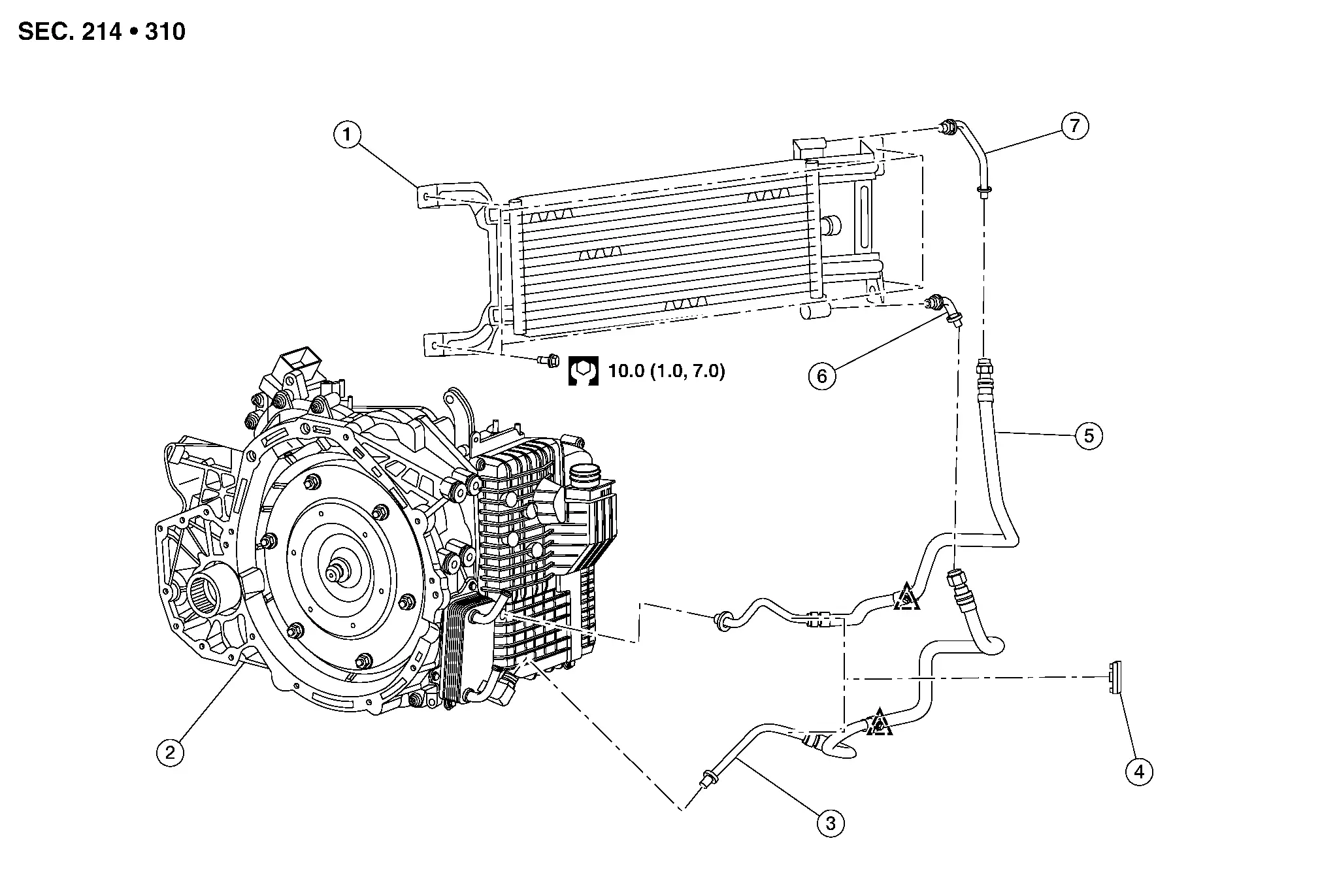
| 1. | A/T fluid cooler | 2. | Transaxle assembly | 3. | A/T fluid cooler hose A |
| 4. | Hose clamp | 5. | A/T fluid cooler hose B | 6. | A/T fluid cooler tube A |
| 7. | A/T fluid cooler tube B |
 |
Clip |
Cleaning
A/T Fluid Cooler Flush
CAUTION:
Metal debris and friction material may become trapped in the radiator, cooling hoses, bypass valve or external A/T fluid cooler (if equipped). This debris can contaminate a newly serviced transmission, control valve or torque converter. In severe cases this debris can block or restrict flow and may cause damage to a newly serviced A/T.
Always perform a A/T Fluid Cooler Flush after any one of the following:
-
A/T (transaxle) assembly overhaul, internal repair or replacement
-
Control valve replacement
-
Torque converter replacement
A/T FLUID COOLER CLEANING PROCEDURE — WITH TOW PACKAGE
Remove front under cover. Refer to Removal and Installation.
Position an oil drain pan under the A/T fluid cooler.
Position an oil drain pan under the A/T fluid warmer.
Disconnect the A/T fluid cooler hose A and A/T fluid cooler hose B from the A/T fluid warmer. Refer to Exploded View.
 NOTE:
NOTE:
-
If rubber material from cooler hose remains on the steel tube or fitting, clean steel tube and replace rubber hose.
-
The hoses removed from the A/T fluid warmer will be flushed first in one direction and then the other.
Allow any transmission fluid that remains in the A/T fluid cooler hoses to drain into the oil drain pan.
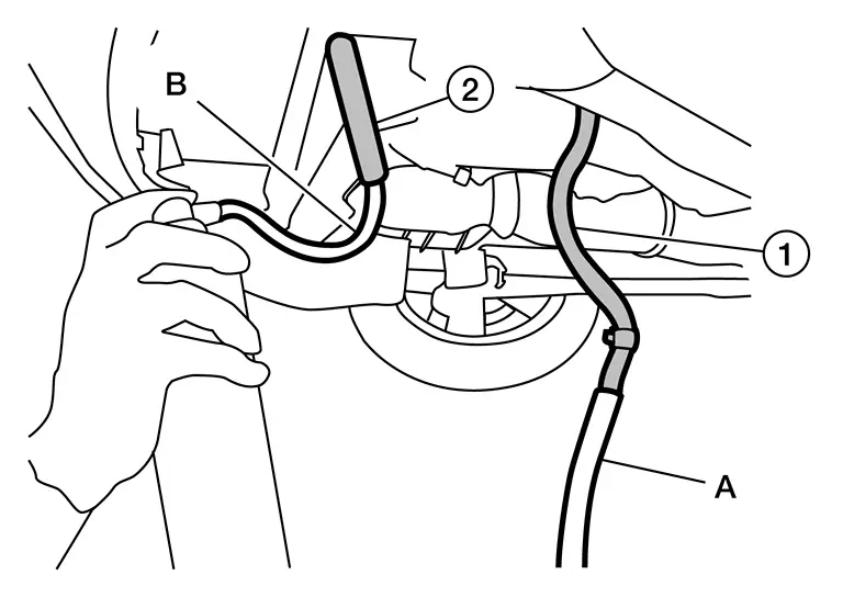
Flush A/T fluid cooler (radiator) and hoses using the following steps:Attach a suitable hose (A) to the A/T fluid cooler hose (1).
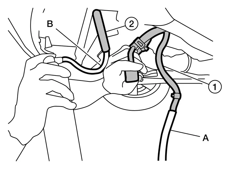
| Hose inside diameter | : 16 mm (5/8 in) |
CAUTION:
-
Wear safety glasses and rubber gloves when spraying the Transmission Cooler Cleaner.
-
Spray Cooler Cleaner only in areas with adequate ventilation.
-
Avoid contact with eyes and skin.
-
Do not breathe vapors or mist from spray.
 NOTE:
NOTE:
Always check with the Parts Department for latest parts information.
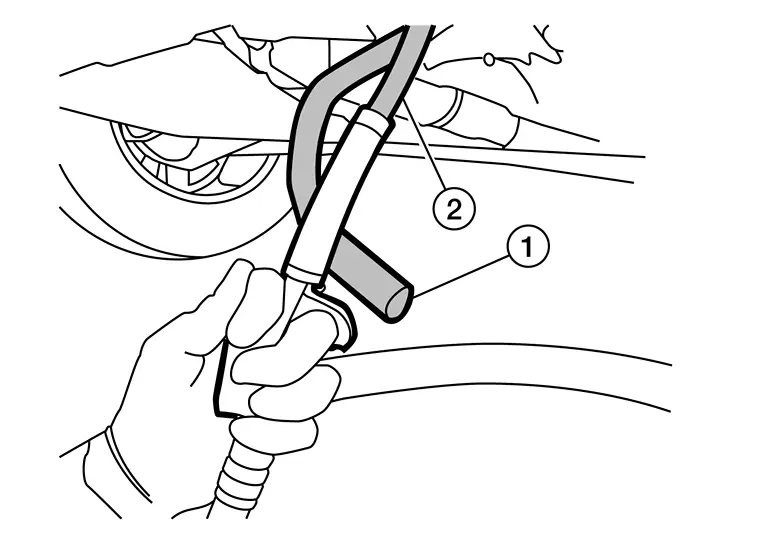
Holding the can and hose as high as possible, spray Transmission Cooler Cleaner in a continuous stream into the A/T fluid cooler (radiator) inlet side hose until it flows from the outlet side hose for five seconds.Attach a suitable hose over the end of the A/T fluid cooler hose (2) that was used as the flush inlet.
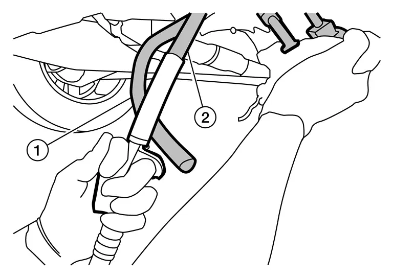
| Hose inside diameter | : 16 mm (5/8 in) |
Blow compressed air through A/T fluid cooler hose (2) for 10 seconds to force remaining fluid out of A/T fluid cooler hose (1).
| Air pressure | : 490-883 kPa (5-9 kg/cm2, 70-128 psi) |
Repeat steps 6-8 one additional time, then proceed to step 10.
Reverse flush the A/T fluid cooler. Install Transmission Cooler Cleaner to A/T fluid cooler hose (1), then reverse flush A/T fluid cooler by repeating steps 6-8 twice.
Remove A/T fluid cooler. Refer to Removal and Installation.
Install suitable hoses onto the inlet side and outlet side of the A/T fluid cooler.
| Hose inside diameter | : 16 mm (5/8 in) |
|---|---|
| Inlet side hose (A) | : 102 mm (4 in) |
| Outlet side hose (B) | : 152 mm (6 in) |
 NOTE:
NOTE:
Position end of suitable hose (B) into a oil drain pan.
Insert the extension adapter hose from a can of Transmission Cooler Cleaner through inlet side of A/T fluid cooler letting cleaner drain through outlet side.
 NOTE:
NOTE:
-
Use one full can of Transmission Cooler Cleaner.
-
Allow fluid to drain from the A/T fluid cooler.
Remove suitable hoses from inlet side and outlet side of A/T fluid cooler.
Insert the tip of air gun into the end of the A/T fluid cooler inlet side (A).
 NOTE:
NOTE:
Wrap a shop rag around the air gun tip and end of the A/T cooler inlet side, to reduce blowback.
Remove any remaining fluid using compressed air at the inlet side of A/T fluid cooler for 10 seconds.
| Air pressure | : 490-883 kPa (5-9 kg/cm2, 70-128 psi) |
Install suitable hoses onto the inlet side and outlet side of the A/T fluid cooler.
| Hose inside diameter | : 16 mm (5/8 in) |
|---|---|
| Inlet side hose (A) | : 102 mm (4 in) |
| Outlet side hose (B) | : 152 mm (6 in) |
 NOTE:
NOTE:
Position end of suitable hose into a oil drain pan.
While holding the hoses securely to the fluid cooler, flush two full quarts of NISSAN Matic R ATF (or equivalent) with a 1-pint suction gun.
 NOTE:
NOTE:
-
Flush from inlet side of the A/T fluid cooler through outlet side of the A/T fluid cooler (auxiliary).
-
Allow the remaining fluid in the A/T fluid cooler to drain out.
Remove suitable hoses from inlet side and outlet side of A/T fluid cooler.
Insert the tip of air gun into A/T fluid cooler inlet side.
 NOTE:
NOTE:
Wrap a shop rag around air gun tip and end of A/T fluid cooler inlet side, to reduce blowback.
Remove any remaining NISSAN Matic R ATF (or equivalent) using compressed air at the inlet side of A/T fluid cooler for 10 seconds.
| Air pressure | : 490-883 kPa (5-9 kg/cm2, 70-128 psi) |
Install A/T fluid cooler hose A and A/T fluid cooler hose B, to A/T fluid warmer. Refer to Exploded View.
Fill the transaxle assembly with A/T fluid. Refer to Replacement.
A/T FLUID COOLER CLEANING PROCEDURE — WITHOUT TOW PACKAGE
CAUTION:
-
Wear safety glasses and rubber gloves when spraying the Transmission Cooler Cleaner.
-
Spray Cooler Cleaner only in areas with adequate ventilation.
-
Avoid contact with eyes and skin.
-
Do not breathe vapors or mist from spray.
Remove front under cover. Refer to Removal and Installation.
Position an oil drain pan under the radiator.
Position an oil drain pan under the A/T fluid warmer.
Disconnect the A/T fluid cooler hose A and A/T fluid cooler hose B from the A/T fluid warmer. Refer to Exploded View.
 NOTE:
NOTE:
The hoses removed from the A/T fluid warmer will be flushed first in one direction and then the other.
Allow any transmission fluid that remains in the A/T fluid cooler hoses to drain into the oil drain pan.
Flush A/T fluid cooler and hoses using the following steps:Attach a suitable hose (A) to the A/T fluid cooler hose (1).
| Hose inside diameter | : 16mm (5/8 in) |
CAUTION:
-
Wear safety glasses and rubber gloves when spraying the Transmission Cooler Cleaner.
-
Spray Cooler Cleaner only in areas with adequate ventilation.
-
Avoid contact with eyes and skin.
-
Do not breathe vapors or mist from spray.
 NOTE:
NOTE:
Always check with the Parts Department for latest parts information.
Holding the can and hose as high as possible, spray Transmission Cooler Cleaner in a continuous stream into the radiator inlet side hose until it flows from the outlet side hose for five seconds.Attach a suitable hose over the end of the A/T fluid cooler hose (2) that was used as the flush inlet.
| Hose inside diameter | : 16mm (5/8 in) |
Blow compressed air through A/T fluid cooler hose (2) for 10 seconds to force remaining fluid out of A/T fluid cooler hose (1).
| Air pressure | : 490-883 kPa (5-9 kg/cm2, 70-128 psi) |
Repeat steps 6-8 one additional time, then proceed to step 10.
Reverse flush the A/T fluid cooler. Install Transmission Cooler Cleaner to A/T fluid cooler hose (1), then repeat steps 6-8 twice.
Install A/T fluid cooler hose A and A/T fluid cooler hose B to the A/T fluid warmer. Refer to Exploded View.
Fill the transaxle assembly with A/T fluid. Refer to Replacement.
Inspection
After performing all procedures, ensure that all remaining oil is cleaned from all components.
A/t Position Nissan Pathfinder
Inspection
CHECK SELECTOR LEVER OPERATION
-
Shift the selector lever and check for excessive effort, sticking, noise or rattle.
-
The selector lever automatically moves back to the H (home) position after it is operated.
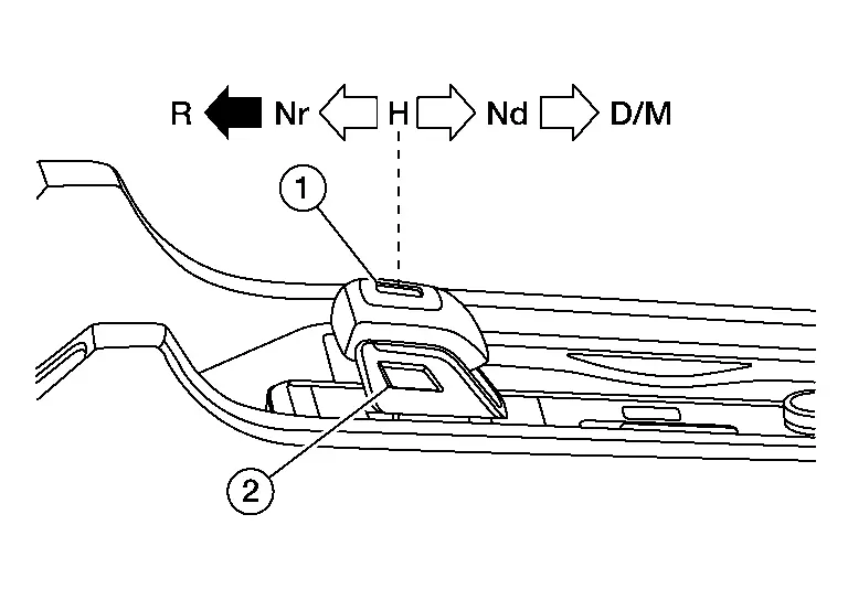
 : P position switch
 : Press the button
 to shift
 : Shift without pressing the button

-
The selector lever cannot move to R position unless press the knob button.
Is the inspection result normal?
YES>>GO TO 2.
NO>>Repair or replace the electric shift selector. Refer to Removal and Installation.
CHECK SHIFT POSITION
Check the following during engine running.
-
When the selector lever shifts to each position during depressing the brake pedal, the shift position normally changes.
-
When the brake pedal is not depressed at the P position, the shift position does not change even if the selector lever is operated.
-
When the P position switch is pressed and released at any shift position except the P position, the shift position changes into the P position.
-
When the selector lever shifts to the D position again at the D position, the shift position changes into the M mode.
-
When the selector lever shifts to the D position again at the M mode, the shift position changes into the D position.
-
When the ignition switch turns off, the shift position automatically changes into the P position. (The selector indicator lamp of the P position turns ON.)
Is the inspection result normal?
YES>>INSPECTION END
NO>>Check the electric shift system.
How to Erase Permanent Dtc Nissan Pathfinder 5th Gen
Description
WHEN A DTC IS STORED IN TCM
When a DTC is stored in TCM and MIL is ON, a permanent DTC is erased with MIL shutoff if the same malfunction is not detected after performing the driving pattern for MIL shutoff three times in a raw.
 NOTE:
NOTE:
The following timing chart is for DTC of two trip detection diagnosis.
In case of DTC of one trip detection diagnosis, when NG is detected at one trip, MIL turns ON and permanent DTC is displayed.
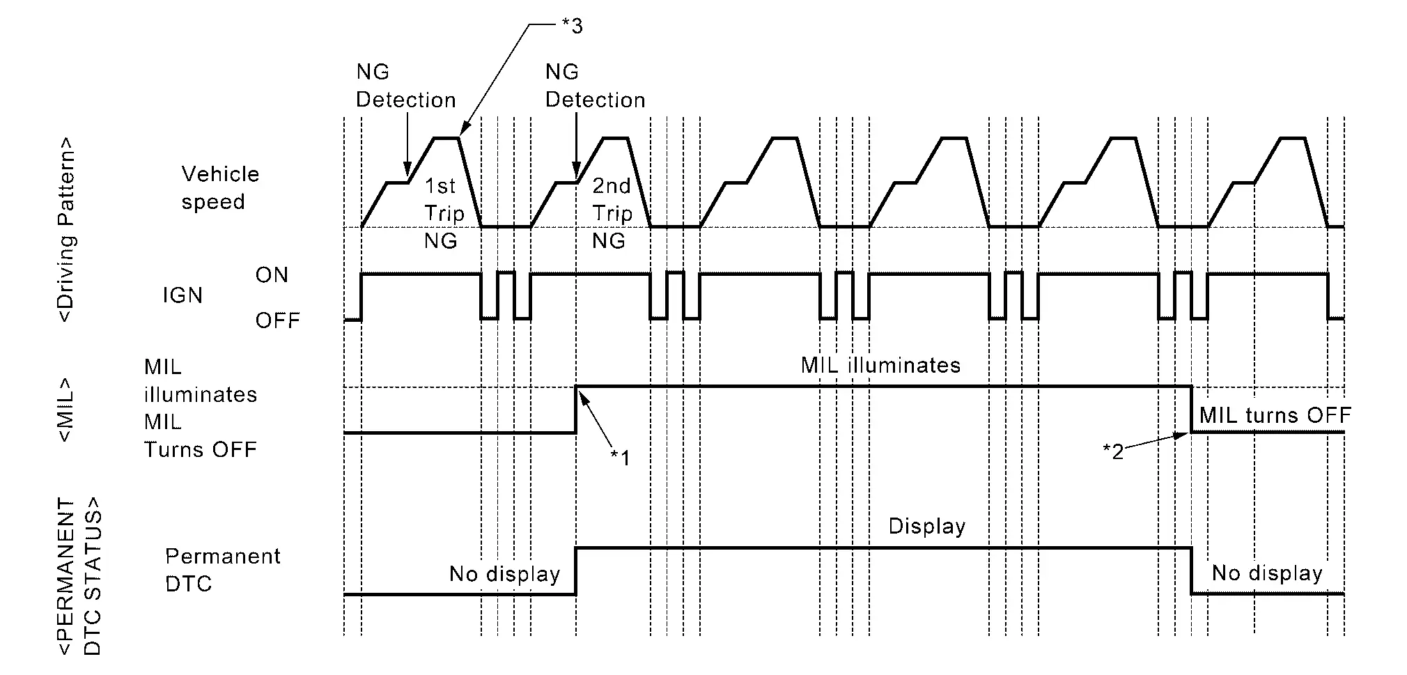
| *1: | When the same malfunction is detected in two consecutive trips, MIL will illuminate. | *2: | MIL will turn off after Nissan Pathfinder vehicle is driven 3 times (driving pattern B) without any malfunctions. | *3: |
Diagnosis condition *A and diagnosis delay time *A for each DTC are satisfied. (*A: For details of these, refer to DTC/CIRCUIT DIAGNOSIS >> DTC (Pxxxx or Uxxx) >> DTC Description >> DTC DETECTION LOGIC.) |
WHEN A DTC IS NOT STORED IN TCM
The erasing method depends on a permanent DTC stored in TCM.
For erase procedure of permanent DTC, refer to Work Procedure.
PERMANENT DTC ITEM
For permanent DTC items, MIL turns ON. Refer to DTC Index.
Work Procedure
CHECK DTC
Check DTC.
Is any DTC detected?
YES>>Repair malfunction(s) and erase DTC.
NO>>GO TO 2.
CHECK PERMANENT DTC
 With CONSULT
-
Ignition switch OFF and wait at least 60 seconds.
-
Ignition switch ON.
-
Ignition switch OFF and wait at least 60 seconds.
-
Ignition switch ON.
-
Select “PERMANENT DTC STATUS” mode with CONSULT.
 With GST
-
Ignition switch OFF and wait at least 60 seconds.
-
Ignition switch ON.
-
Ignition switch OFF and wait at least 60 seconds.
-
Ignition switch ON.
-
Select Service $0A with GST.
Is any permanent DTC detected?
YES>>GO TO 3.
NO>>END
HOW TO ERASE PERMANENT DTC
CAUTION:
Always drive at a safe speed.
-
Perform "DTC CONFIRMATION PROCEDURE "of detected permanent DTC.
-
Drive the Nissan Pathfinder vehicle following to driving pattern.
-
The state of driving at 40 km/h (25 MPH) reaches 300 seconds or more in total.
-
Idle speed lasts 30 seconds or more.
-
A lapse of 600 seconds or more after engine start.
-
>>
GO TO 4.
CHECK PERMANENT DTC
 With CONSULT
-
Ignition switch OFF and wait at least 60 seconds.
-
Ignition switch ON.
-
Ignition switch OFF and wait at least 60 seconds.
-
Ignition switch ON.
-
Select “PERMANENT DTC STATUS” mode with CONSULT.
 With GST
-
Ignition switch OFF and wait at least 60 seconds.
-
Ignition switch ON.
-
Ignition switch OFF and wait at least 60 seconds.
-
Ignition switch ON.
-
Select Service $0A with GST.
Is any permanent DTC detected?
YES>>GO TO 1.
NO>>END

Nissan Pathfinder (R53) 2022-2026 Service Manual
Basic Inspection
- Diagnosis and Repair Work Flow
- Additional Service When Replacing Tcm
- Additional Service When Replacing Transaxle Assembly
- Additional Service When Replacing Control Valve
- Dog Clutch Position Sensor Calibration
- Learning of Solenoid Characteristic
- A/t Clutch Touch Point Learning
- Mac Key Writing
- A/t Fluid Cooler System
- A/t Position
- How to Erase Permanent Dtc
Contact Us
Nissan Pathfinder Info Center
Email: info@nipathfinder.com
Phone: +1 (800) 123-4567
Address: 123 Pathfinder Blvd, Nashville, TN 37214, USA
Working Hours: Mon–Fri, 9:00 AM – 5:00 PM (EST)
