Nissan Pathfinder: Automatic Drive Positioner - System
- Automatic Drive Positioner
- Manual Function
- Memory Function
- Exit Assist Function
- Entry Assist Function
- Intelligent Key Interlock Function
Automatic Drive Positioner Nissan Pathfinder Fifth generation
System Description
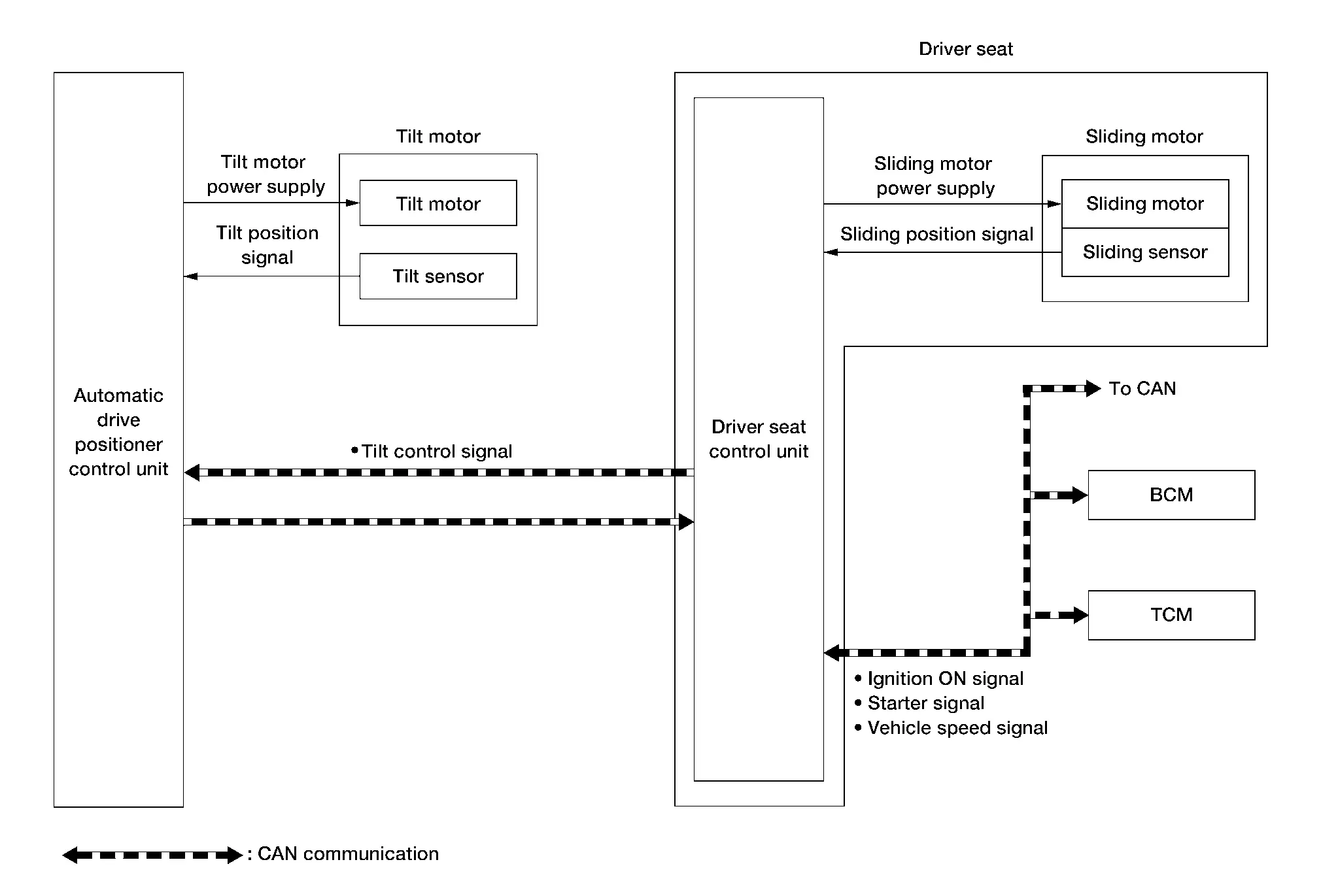
SYSTEM DIAGRAM
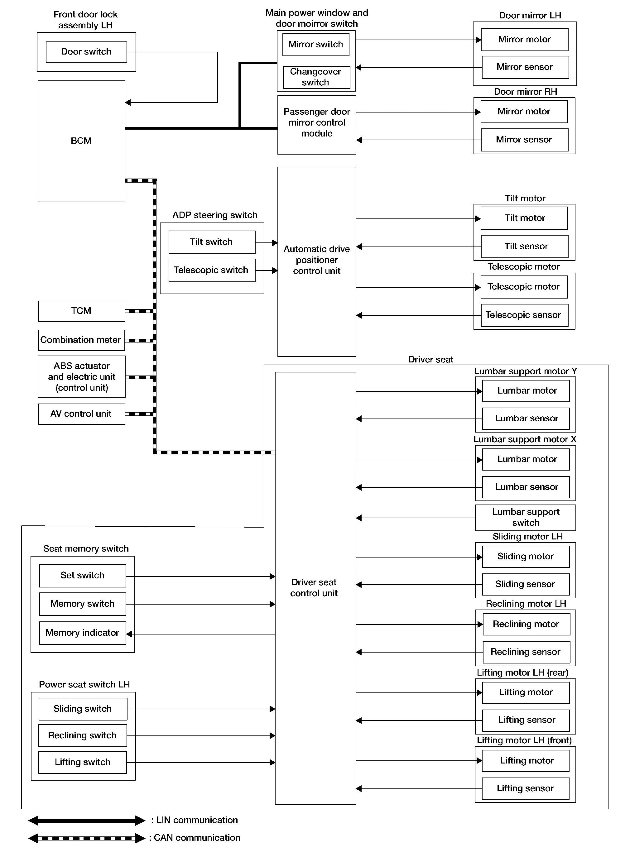
INPUT SIGNAL AND OUTPUT SIGNAL
Several types of signals are transmitted from the following units to the driver seat control unit via CAN communication:
| Component | Signal |
|---|---|
| ABS actuator and electric unit (control unit) | Nissan Pathfinder Vehicle speed signal |
| Combination meter | Vehicle speed signal |
| BCM |
|
| TCM | Electronic shift selector signal |
System Description
OUTLINE
The system automatically moves the driver seat, steering column and door mirror position by the driver seat control unit and the automatic drive positioner control unit. The driver seat control unit corresponds with the automatic drive positioner control unit via CAN communication.
| Function | Description | |
|---|---|---|
| Manual function | The driving position (seat, steering column and door mirror position) can be adjusted by using the power seat switch, lumbar support switch, ADP steering switch or door mirror control switch. | |
| Memory function | The seat, steering column and door mirror move to the stored driving position by pressing seat memory switch (1 or 2). | |
| Entry/Exit assist function | Exit | On exit, the seat moves backward and the steering column moves upward. |
| Entry | On entry, the seat and steering column returns from exiting position to the previous driving position. | |
| Intelligent Key interlock function | Perform memory operation, exiting operation and entry operation by Intelligent Key unlock operation or driver side door request switch unlock operation. | |
Manual Function Nissan Pathfinder
System Description
SYSTEM DIAGRAM
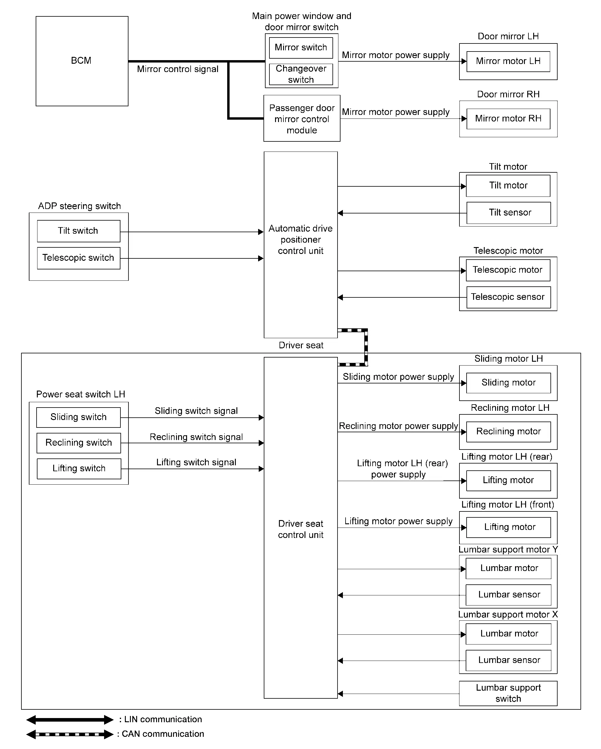
INPUT SIGNAL AND OUTPUT SIGNAL
The following signal is transmitted from the following unit to the driver seat control unit via CAN communication:
| Component | Signal |
|---|---|
| BCM | Ignition switch signal |
System Description
OUTLINE
The driving position (seat, steering column and door mirror position) can be adjusted manually with power seat switch LH, lumbar support switch, ADP steering switch and door mirror remote control switch.
OPERATION PROCEDURE
-
Ignition switch ON.
-
Operate power seat switch LH, lumbar support switch, ADP steering switch or door mirror remote control switch.
-
The driver seat, steering column or door mirror operates according to the operation of each switch.
DETAIL FLOW
Seat
| Order | Input | Output | Control unit condition |
|---|---|---|---|
| 1 |
Power seat switch LH (sliding, lifting, reclining) |
— | The power seat switch LH signal is inputted to the driver seat control unit when the power seat switch LH is operated. |
| 2 | Lumbar support switch | — | The lumbar support switch signal is inputted to the driver seat control unit when the lumbar support switch is operated. |
| 3 | — |
Motors (sliding LH, lifting LH (front), lifting LH (rear), reclining LH, lumbar support motor X, lumbar support motor Y) |
The driver seat control unit outputs signals to each motor according to the power seat switch LH, or lumbar support switch, input signal. |
Tilt and Telescopic
| Order | Input | Output | Control unit condition |
|---|---|---|---|
| 1 | ADP steering switch | — | The ADP steering switch signal is inputted to the automatic drive positioner control unit when the ADP steering switch is operated. |
| 2 | — |
Motors (tilt, telescopic) |
The automatic drive positioner control unit actuates the motors according to the operation of the ADP steering switch signal. |
| 3 |
Sensors (tilt, telescopic) |
— | The automatic drive positioner control unit recognizes any operation limit of each actuator via each sensor and will not operate the motors anymore at that time. |
Door Mirror
| Order | Input | Output | Control unit condition |
|---|---|---|---|
| 1 | Door mirror switch | — | The door mirror control switch signal is inputted to the main power window and door mirror switch, or passenger door mirror control module, when the door mirror control switch is operated. |
| 2 | — |
Motors (Door mirror motor) |
The main power window and door mirror switch, or passenger door mirror control module, actuates each motor according to the operation of the door mirror remote control switch. |
 NOTE:
NOTE:
The door mirrors can be operated manually when ignition switch is in either ACC or ON position. The ignition switch signal (ACC/ON) is transmitted from BCM to the main power window and door mirror switch, or passenger door mirror control module, via LIN communication .
Memory Function Nissan Pathfinder
System Description
SYSTEM DIAGRAM
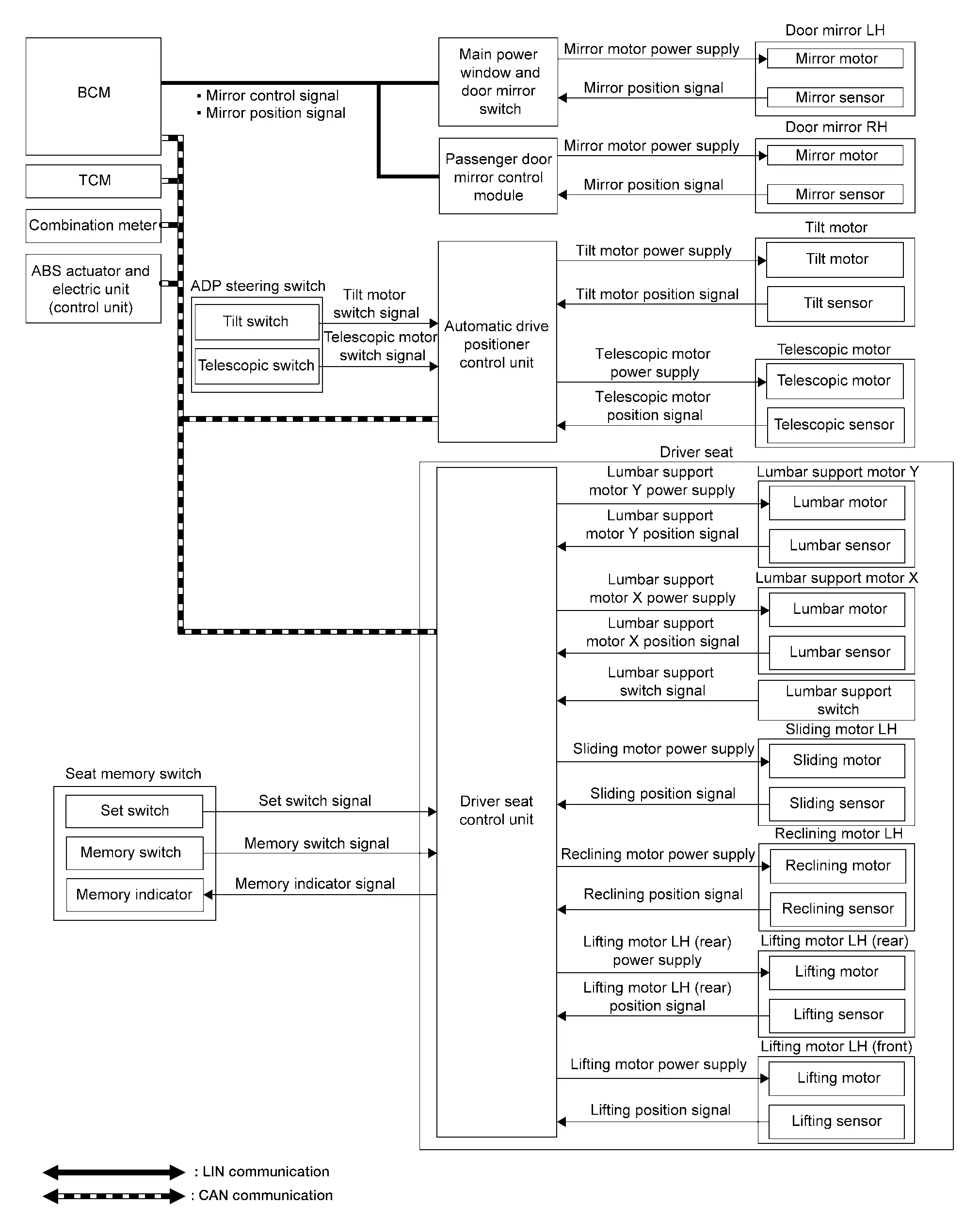
INPUT SIGNAL AND OUTPUT SIGNAL
Several types of signals are transmitted from the following units to the driver seat control unit via CAN communication:
| Component | Signal |
|---|---|
| ABS actuator and electric unit (control unit) | Nissan Pathfinder Vehicle speed signal |
| Combination meter | Vehicle speed signal |
| BCM | Ignition switch signal |
System Description
OUTLINE
The driver seat control unit can store the optimum driving positions [seat, steering column and door mirror position] for 2 people. If the front seat position is changed, one-touch (pressing desired memory switch) operation allows changing to the other driving position.
 NOTE:
NOTE:
For further information for the memory storage procedure, refer to Owner’s Manual.
OPERATION PROCEDURE
-
Ignition switch ON.
-
Press desired memory switch.
-
Front seat LH, steering column and door mirror will move to the memorized position.
OPERATION CONDITION
Satisfy all of the following items. The memory function is not performed if these items are not satisfied:
| Item | Request status |
|---|---|
| Ignition position | ON |
|
Switch inputs
|
OFF (Not operated) |
| Electric shift selector | P position |
However, the memory operation can be performed for 45 seconds after opening the front door LH (front door switch LH OFF → ON) even if the ignition switch is OFF.
DETAIL FLOW
| Order | Input | Output | Control unit condition |
|---|---|---|---|
| 1 | Memory switch | — | The memory switch signal is inputted to the driver seat control unit when memory switch 1 or 2 is operated. |
| 2 | — |
Motors (Seat, door mirror) |
Driver seat control unit operates each motor of seat when it recognizes the memory switch pressed for 0.5 second or more and requests each motor operation to BCM via CAN communication. The BCM transmits mirror control signal to main power window and door mirror switch and passenger door mirror control module via LIN communication and actuates each motor according to the operation of the door mirror remote control switch. |
| Memory switch Indicator | Driver seat control unit requests the flashing of memory indicator while either of the motors is operating. The driver seat control unit illuminates the memory indicator. | ||
| 3 |
Sensors (Seat, door mirror) |
— | Driver seat control unit judges the operating seat position with each seat sensor input. The positions of the door mirror is monitored with mirror sensor signal. Driver seat control unit stops the operation of each motor when each part reaches the recorded address. |
| 4 | — | Memory switch Indicator | Driver seat control unit requests the illumination of memory indicator after all motors stop. The driver seat control unit illuminates the memory indicator for 5 seconds. |
Exit Assist Function Nissan Pathfinder R53
System Description
SYSTEM DIAGRAM
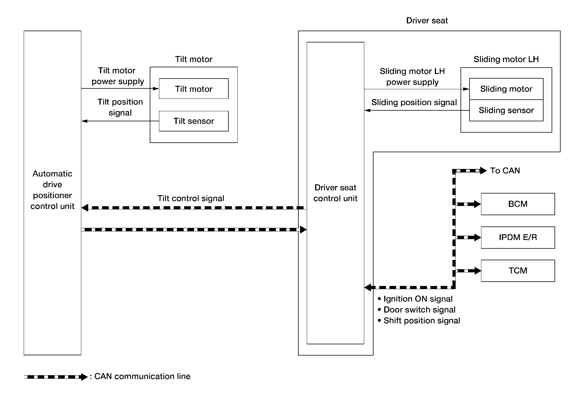
INPUT SIGNAL AND OUTPUT SIGNAL
Several types of signals are transmitted from the following units to the driver seat control unit via CAN communication:
| Component | Signal |
|---|---|
| BCM |
|
| TCM | Shift position signal |
System Description
OUTLINE
When exiting, if the conditions are satisfied, the seat is moved backward from normal sitting position and the steering column is moved up.
The seat slide amount at entry/exit operation can be changed.
 NOTE:
NOTE:
-
This function is set to ON before delivery (initial setting).
-
For further information for the system setting procedure, refer to Owner’s Manual.
OPERATION PROCEDURE
-
Open the front door LH with ignition switch OFF.
-
Front seat LH and steering column will move to the exiting position.
OPERATION CONDITION
Satisfy all of the following items. The exit assist function is not performed if these items are not satisfied:
| Item | Request status |
|---|---|
| Ignition switch | OFF |
| System setting [Entry/exit assist function] | ON |
| Initialization | Done |
|
Switch inputs
|
OFF (Not operated) |
| Electric shift selector | P position |
DETAIL FLOW
| Order | Input | Output | Control unit condition |
|---|---|---|---|
| 1 | Front door switch LH | — | Driver seat control unit receives front door switch LH signal (open) from BCM via CAN communication. |
| 2 | — | Motors [seat sliding LH, tilt )] | Driver seat control unit operates the seat sliding motor LH, which recognizes that the driver side door is opened with ignition switch OFF. Driver seat control unit then requests the operations of tilt motor to automatic drive positioner control unit via CAN communication. The automatic drive positioner control unit operates each motor for a constant amount. |
Entry Assist Function Nissan Pathfinder 2026
System Description
SYSTEM DIAGRAM
INPUT SIGNAL AND OUTPUT SIGNAL
Several types of signals are transmitted from the following units to the driver seat control unit via CAN communication:
| Component | Signal |
|---|---|
| BCM |
|
| TCM | Electric shift selector signal |
OUTLINE
The seat is in the exiting position when either following condition is satisfied, the seat returns from exiting position to the previous driving position:
 NOTE:
NOTE:
-
This function is set to OFF before delivery (initial setting).
-
For further information for the system setting procedure, refer to Owner’s Manual.
OPERATION PROCEDURE
-
Ignition switch ACC.
-
Front seat LH and steering column will return from the exiting position to entry position.
OPERATION CONDITION
Satisfy all of the following items. The entry assist function is not performed if these items are not satisfied:
| Item | Request status |
|---|---|
| Seat, steering column | The Nissan Pathfinder vehicle is not moved after performing the exit assist function. |
|
Switch inputs
|
OFF (Not operated) |
| Electric shift selector | P position |
DETAIL FLOW
| Order | Input | Output | Control unit condition |
|---|---|---|---|
| 1 | Door switch/Ignition switch | — | Driver seat control unit receives the signals of ignition switch signal and front door switch from BCM via CAN communication. |
| 2 | — | Motors [sliding LH, tilt] | Driver seat control unit operates the sliding motor LH when the operating conditions are satisfied and requests the operation of tilt motor (if equipped) to automatic drive positioner control unit via CAN communication. The automatic drive positioner control unit operates the tilt motor. |
| Sensors [sliding, tilt] | — | Each sensor monitors the operating positions of seat and steering column, then stops the operation of motor when each part reaches the recorded address. |
Intelligent Key Interlock Function Nissan Pathfinder 2022
System Description
SYSTEM DIAGRAM
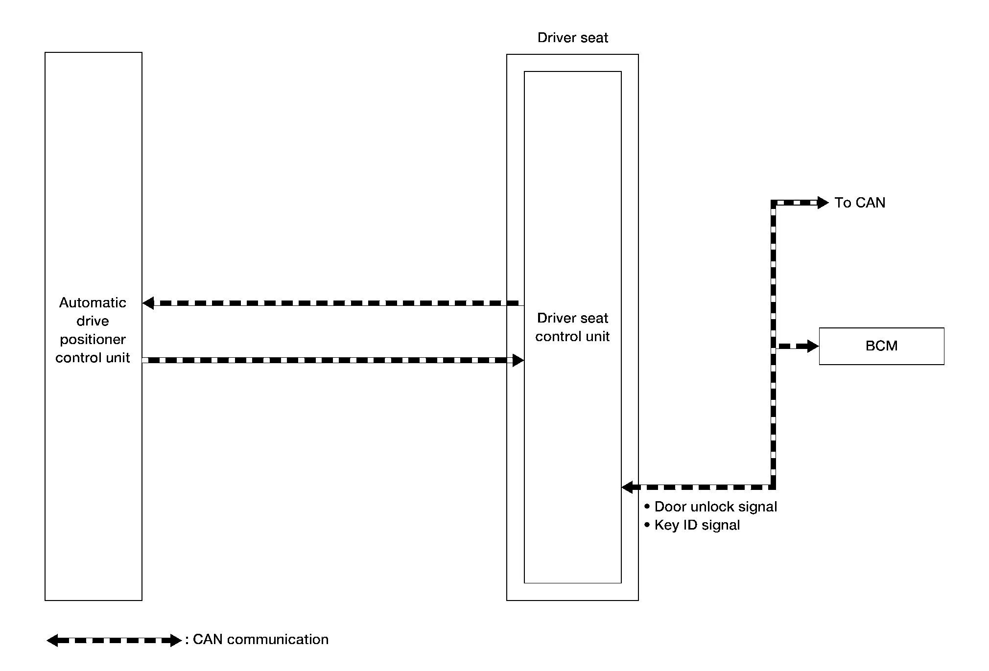
INPUT SIGNAL AND OUTPUT SIGNAL
Several types of signal are transmitted from the following units to the driver seat control unit via CAN communication:
| Component | Signal |
|---|---|
| BCM |
|
System Description
-
By associating Intelligent Key and automatic drive positioner system, the unlock operation of Intelligent Key or driver side door request switch performs memory function and entry/exit assist function.
-
Registration of Intelligent Key interlock function can register a different key ID to the driver seat control unit, one by one, for memory switch 1 and 2. A total of 2 key IDs can be registered.
-
When ignition switch is OFF, and door unlock operation is performed using Intelligent Key or driver side door request switch, driver seat automatically adjusts to a driving position other than seat sliding. Seat sliding and steering column tilt perform return operation and are set to standby status.
-
In standby status, when ignition switch is placed from OFF to ACC, return operation sets seat sliding and steering column tilt to a registered position.
 NOTE:
NOTE:
-
When another key ID is newly registered to a key switch to which a key ID is already registered, the previously registered key ID is overwritten and becomes unusable.
-
When starter signal turns ON during return operation, the operation is interrupted, starter signal turns from ON to OFF, and operation restarts.
OPERATION PROCEDURE
-
Unlock driver door by Intelligent Key or front LH door request switch.
-
Operation other than memory function of seat sliding is performed. Seat sliding and steering column tilt perform exit assist operation.
-
Ignition switch ACC.
-
Driver seat and steering column will return from the exiting position to entry position.
 NOTE:
NOTE:
Further information for Intelligent Key interlock function. Refer to Description.
OPERATION CONDITION
Satisfy all of the following items. The Intelligent Key interlock function is not performed if these items are not satisfied:
| Item | Request status |
|---|---|
| Ignition position | OFF |
| Intelligent Key interlock function | Registered |
|
Switch inputs
|
OFF (Not operated) |
| Electric shift selector | P position |
DETAIL FLOW
| Order | Input | Output | Control unit condition |
|---|---|---|---|
| 1 |
|
— | Driver seat control unit receives the door unlock signal and the key ID signal from BCM when unlocking the door with Intelligent Key or driver side door request switch. |
| 2 | — | — | Driver seat control unit performs the seat slide and steering tilt move directly to the exit assist function. Other loads move to the exit assist function after performing memory function. |
| 3 | — | — | Driver seat control unit performs the entry assist function. |

Nissan Pathfinder (R53) 2022-2026 Service Manual
System
- Automatic Drive Positioner
- Manual Function
- Memory Function
- Exit Assist Function
- Entry Assist Function
- Intelligent Key Interlock Function
Contact Us
Nissan Pathfinder Info Center
Email: info@nipathfinder.com
Phone: +1 (800) 123-4567
Address: 123 Pathfinder Blvd, Nashville, TN 37214, USA
Working Hours: Mon–Fri, 9:00 AM – 5:00 PM (EST)
