Nissan Pathfinder: Heater & Air Conditioning System - Component Parts
Component Parts Location
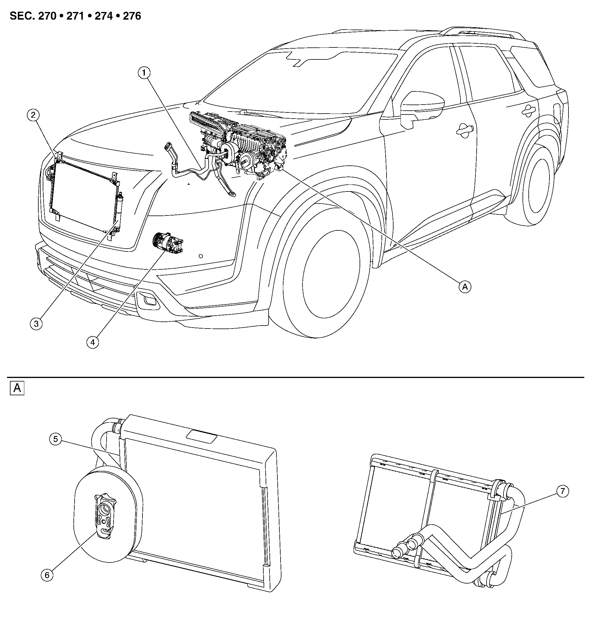
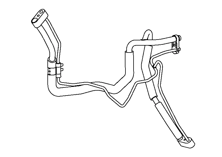
| 1. | Low-pressure pipe | Refer to High-Pressure and Low-Pressure Pipe. |
| 2. | Condenser | Refer to Condenser. |
| 3. | Liquid tank | Refer to Liquid Tank. |
| 4. | Compressor | Refer to Compressor. |
| 5. | Evaporator | Refer to Evaporator. |
| 6. | Expansion valve | Refer to Expansion Valve. |
| 7. | Heater core | Refer to Heater Core. |
| A. | Heating and cooling unit assembly | Refer to Heating and Cooling Unit Assembly. |
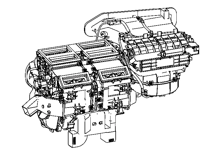
Heating and Cooling Unit Assembly
This system utilizes a heating and cooling unit that combines the heating unit and cooling unit into an assembly.
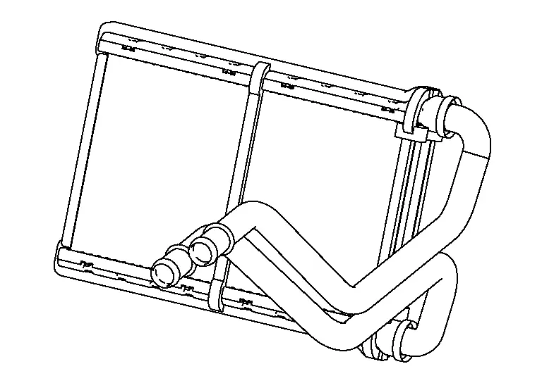
Heater Core
Hot coolant from the engine is passed through a winding tube of the core. Fins attached to the core tubes serve to increase surface for heat transfer to air that is forced past them, by a fan, thereby heating the passenger compartment.
Expansion Valve
Refrigerant temperature is detected by the temperature sensing part, located in the low-pressure refrigerant path inside the expansion valve. The lift amount of the high-pressure side ball valve is changed to regulate the refrigerant flow.
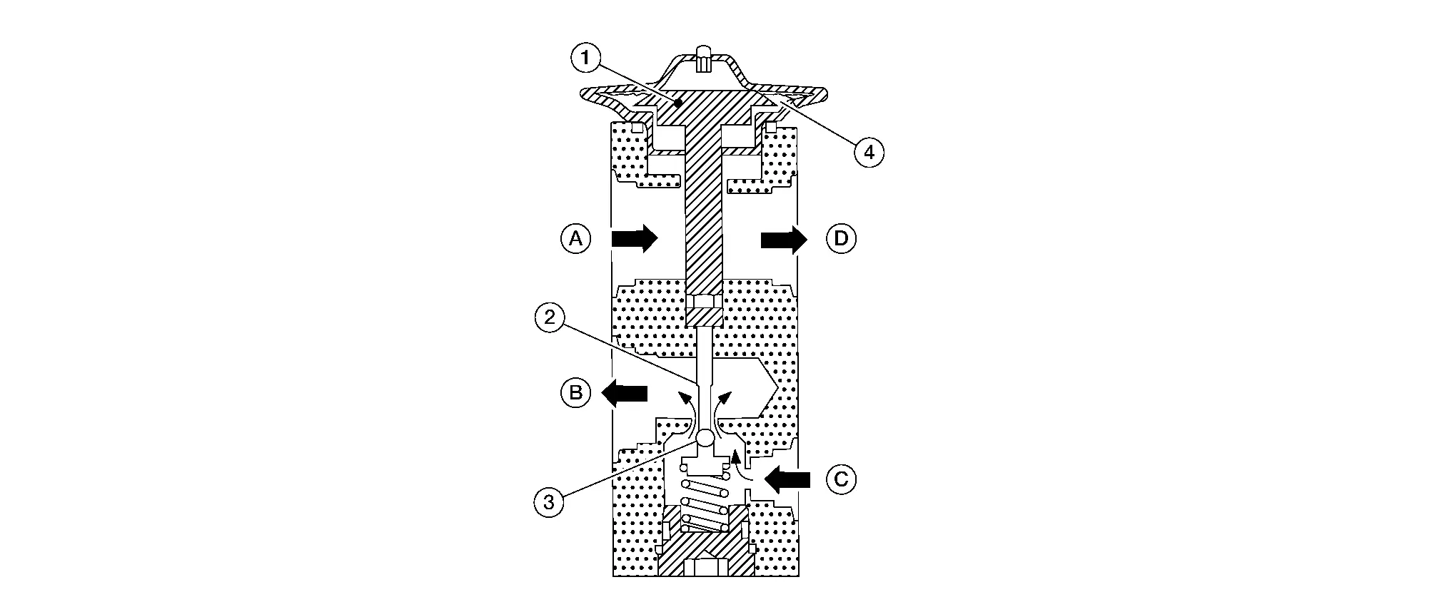
| 1. | Sensing part | 2. | Shaft | 3. | Ball valve |
| 4. | Diaphragm | ||||
| A. | From evaporator (low-pressure side) | B. | To evaporator (high-pressure side) | C. | From liquid tank |
| D. | To electric compressor | ||||
 |
Refrigerant flow |
Evaporator
-
A thin laminate pipeless evaporator is used.
-
The mist from liquid refrigerant transforms to gas by evaporation by the air conveyed from front blower motor. The air is cooled by the heat by evaporation.
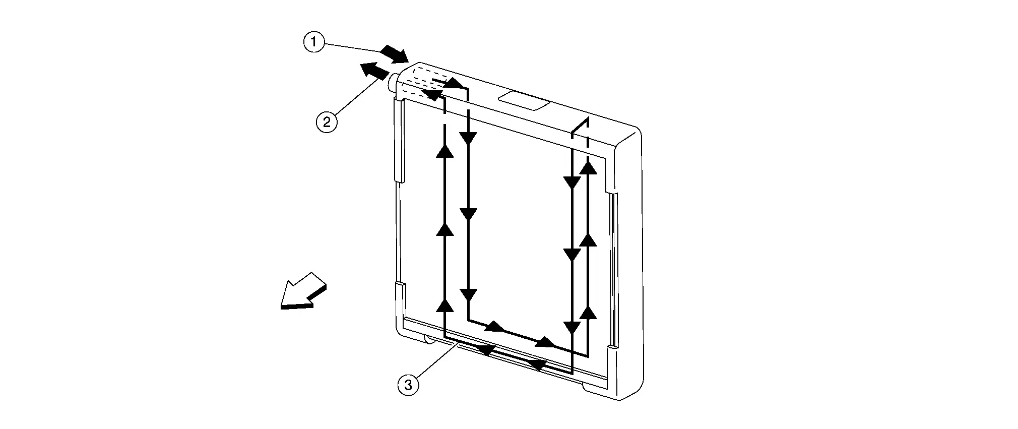
1. Inlet 2. Outlet 3. Refrigerant flow 
Front
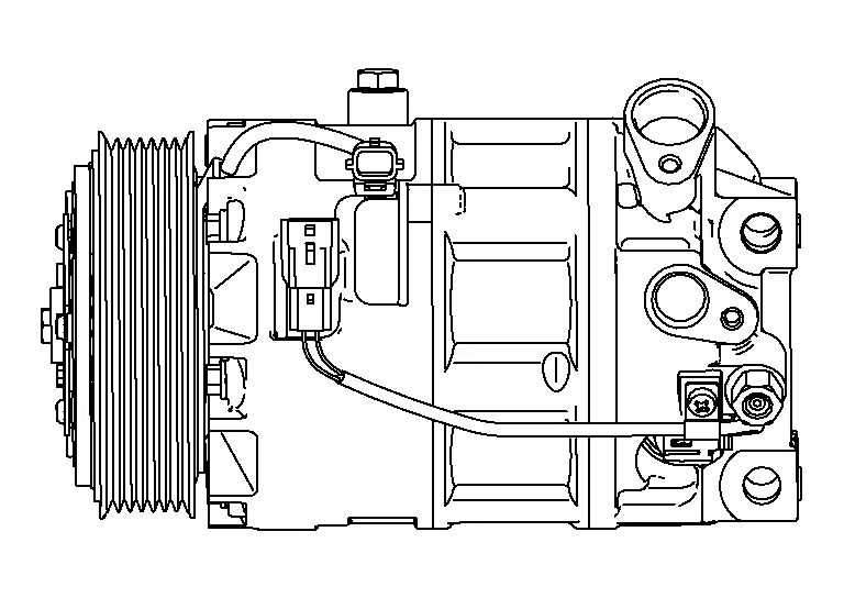
Compressor
Intakes, compresses, and discharges refrigerant to circulate refrigerant inside the refrigerant cycle.
Condenser
The sub-cool section further cools the liquid refrigerant, increasing the amount of heat that the liquid refrigerant can absorb and improving cooling performance.
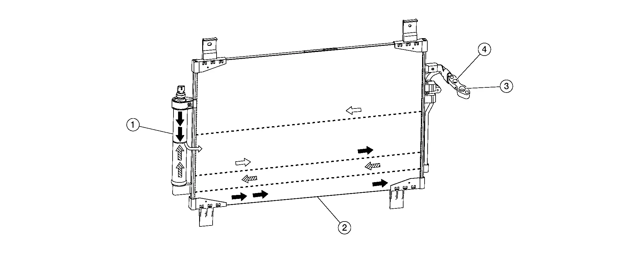
| 1. | Liquid tank | 2. | Sub cool part (over cool part) | 3. | Inlet |
| 4. | Outlet | ||||
 |
Gas refrigerant |
 |
Gas and liquid |
 |
Liquid |
Liquid Tank
-
A liquid tank compatible with R-1234yf refrigerant is used.
-
Eliminates foreign matter in refrigerant and temporarily stores liquid refrigerant.
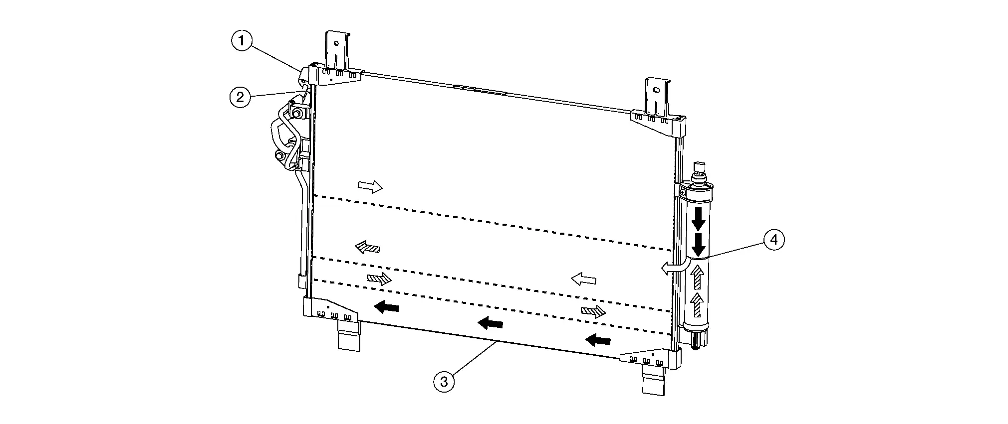
| 1. | Outlet | 2. | Inlet | 3. | Sub cool part (over cool part) |
| 4. | Liquid tank | ||||
 |
Gas refrigerant |
 |
Gas and liquid |
 |
Liquid |
High-Pressure and Low-Pressure Pipe
Transfers heat out of the liquid refrigerant, sub cooling it below condensation temperature.
Refrigerant Cycle
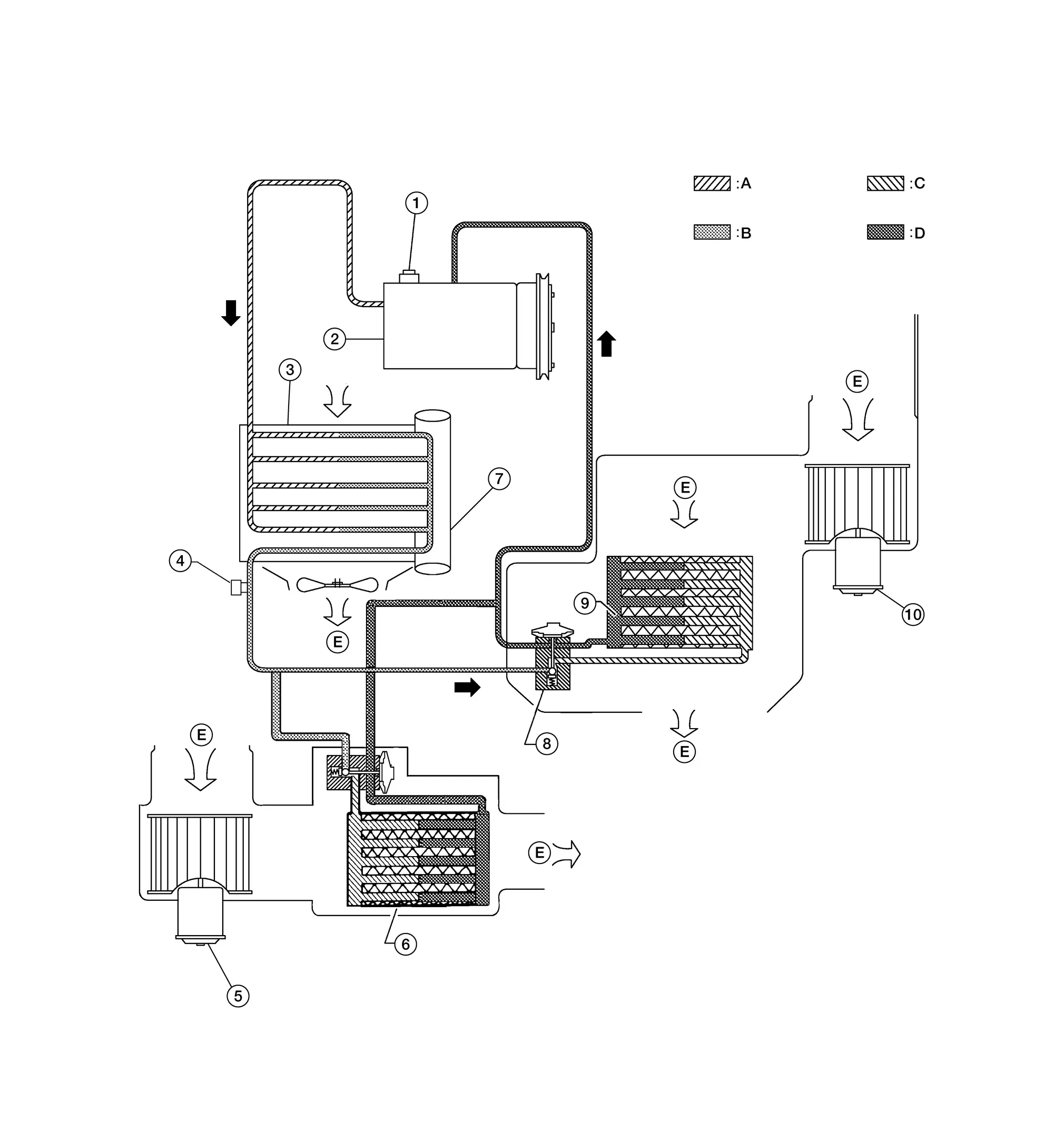
| 1. | Pressure relief valve | 2. | Compressor | 3. | Condenser |
| 4. | Refrigerant pressure sensor | 5. | Front blower motor | 6. | Front evaporator and expansion valve assembly |
| 7. | Liquid tank | 8. | Rear expansion valve | 9. | Rear evaporator |
| 10. | Rear blower motor | ||||
| A. | High-pressure gas | B. | High-pressure liquid | ||
| C. | Low-pressure liquid | D. | Low-pressure gas | E. | Outside air |
Refrigerant System Protection
REFRIGERANT CYCLE
Refrigerant Flow
The refrigerant from the compressor flows through the condenser and liquid tank, evaporator, and returns to the compressor. The refrigerant evaporation in the evaporator is controlled by an expansion valve.
Freeze Protection
To prevent evaporator from freezing up, the evaporator air temperature is monitored and the voltage signal to the A/C auto amp. makes the A/C relay go OFF and stop the compressor.
REFRIGERANT SYSTEM PROTECTION
Refrigerant Pressure Sensor
-
The refrigerant system is protected against excessively high or low pressures by the refrigerant pressure sensor, located on the liquid tank. The refrigerant pressure sensor detects the pressure inside the refrigerant line and sends the voltage signal to the ECM if the system pressure rises above or falls below the specifications.
-
ECM turns the A/C relay to OFF and stops the compressor when the high-pressure side detected by refrigerant pressure sensor to have the following conditions:
-
Approximately 3,120 kPa (31.8 kg/cm2, 452 psi) or more (Engine speed is 1,500 rpm or more.)
-
Approximately 2,740 kPa (27.9 kg/cm2, 397 psi) or more (Engine speed is less than 1,500 rpm.)
-
Approximately 120 kPa (1.2 kg/cm2, 17 psi) or less
-
Pressure Relief Valve
The refrigerant system is also protected by a pressure relief valve, located in the rear head of the compressor. The release port on the pressure relief valve automatically opens and releases refrigerant into the atmosphere when the pressure of refrigerant in the system increases to an unusual level [more than 3,800 kPa (38.8 kg/cm2, 551 psi)].

Nissan Pathfinder (R53) 2022-2026 Service Manual
Contact Us
Nissan Pathfinder Info Center
Email: info@nipathfinder.com
Phone: +1 (800) 123-4567
Address: 123 Pathfinder Blvd, Nashville, TN 37214, USA
Working Hours: Mon–Fri, 9:00 AM – 5:00 PM (EST)
