Nissan Pathfinder: System Description - System ++
Meter System
System Description
SYSTEM DIAGRAM
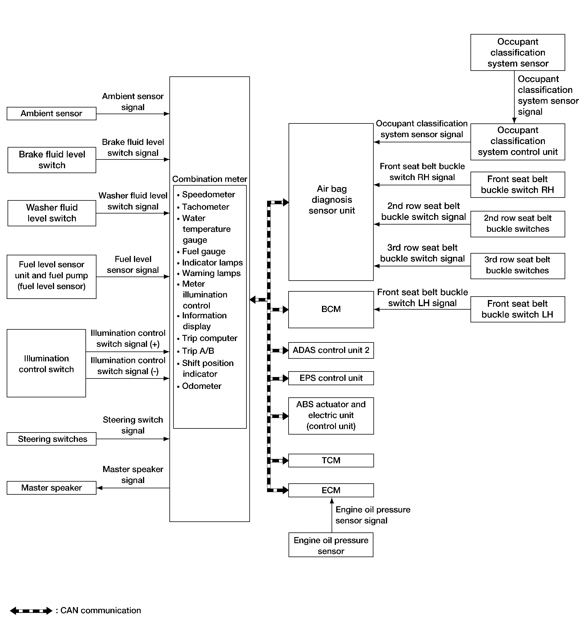
Combination Meter Input Signal (CAN Communication Signal)
| Transmit unit | Signal name |
|---|---|
| BCM | Buzzer output signal |
| Dimmer signal | |
| Door switch signal | |
| Front fog light status signal | |
| High beam assist indicator signal | |
| High beam status signal | |
| Light reminder warning signal | |
| Low beam status signal | |
| Low tire pressure warning lamp signal | |
| Low tire pressure wheel location signal | |
| Position light status signal | |
| Front seat belt buckle switch LH signal | |
| Sleep wake up signal | |
| TPMS malfunction warning lamp signal | |
| ECO advice signal | |
| TCM | Shift position signal |
| Electric shift warning message signal | |
| Electric shift warning lamp signal | |
| Shift P range request display signal | |
| Shift refuse buzzer signal | |
| Neutral hold mode signal | |
| ECM | Battery warning request signal (ECM) |
| ECO mode indicator signal | |
| ECO pedal guide signal | |
| Engine coolant temperature signal | |
| Engine oil pressure warning lamp signal | |
| Engine speed signal | |
| Engine status signal | |
| Fuel consumption monitor signal | |
| Remaining distance signal | |
| Nissan Pathfinder Vehicle speed display signal | |
| EPS (Electric Power Steering) control unit | Power steering warning lamp signal |
| ADAS (Advanced Driver Assistance System) control unit 2 | Buzzer output signal |
| Meter display signal | |
| AEB warning lamp signal | |
| RAB warning lamp signal | |
| Air bag diagnosis sensor unit | Occupant detection signal |
| SRS air bag warning lamp signal | |
| Front seat belt buckle switch RH signal | |
| 2nd row seat belt buckle switch LH signal | |
| 2nd row seat belt buckle switch CTR signal | |
| 2nd row seat belt buckle switch RH signal | |
| 3rd row seat belt buckle switch LH signal | |
| 3rd row seat belt buckle switch CTR signal | |
| 3rd row seat belt buckle switch RH signal | |
| IPDM E/R (Intelligent Power Distribution Module Engine Room) | Battery warning request signal (IPDM E/R) |
| Headlamp warning signal | |
| Starter relay status signal | |
| Intelligent Key unit | Buzzer output signal |
| Meter display signal | |
| Chassis control module | Meter display signal |
| Automatic brake hold indicator lamp signal | |
| Drive mode signal | |
| Around View® Monitor control unit | Buzzer output signal |
| Sonar control unit | Parking sensor error signal |
| Sonar indicator signal | |
| ABS actuator and electric unit (control unit) | ABS warning lamp signal |
| Brake warning lamp signal | |
| Buzzer output signal | |
| Electric parking brake indicator lamp signal | |
| Electric parking brake warning lamp signal | |
| Electric parking brake status signal | |
| Odometer signal | |
| VDC OFF indicator lamp signal | |
| VDC warning lamp signal | |
| 4WD (wheel drive) control unit | 4WD warning display signal |
| Torque distribution indicator signal | |
| Driver seat control unit | Memory guidance display request signal |
DESCRIPTION
Combination Meter
-
The combination meter receives necessary signals from each unit, switch, and sensor to control the following functions:
-
Measuring instruments
-
Speedometer
-
Tachometer
-
Engine coolant temperature gauge
-
Fuel gauge
-
Odometer
-
Distance to empty
-
Clock
-
Ambient temperature
-
-
Warning lamps
-
Indicator lamps
-
Meter illumination control
-
Meter effect function
-
Information display
-
-
The combination meter incorporates a chime function that sounds an audible alarm with the master speaker. For further details, refer to Combination Meter
. -
The combination meter includes an on board diagnosis function.
-
The combination meter can be diagnosed with CONSULT.
METER CONTROL FUNCTION LIST
| System | Description | Reference | |||
|---|---|---|---|---|---|
| Measuring instruments | Speedometer | Indicates Nissan Pathfinder vehicle speed. | System Description | ||
| Tachometer | Indicates engine speed. | System Description | |||
| Engine coolant temperature gauge | Indicates engine coolant temperature. | System Description | |||
| Fuel gauge | Indicates fuel level. | System Description | |||
| Odometer | Indicates the mileage. | System Description | |||
| Distance to empty | Indicates distance to empty. | System Description | |||
| Clock | Indicates current time. | System Description | |||
| Ambient temperature | Indicates ambient temperature. | System Description | |||
| Warning lamp/indicator lamp | The warning lamp/indicator lamp turns ON or turns OFF, according to system malfunction or Nissan Pathfinder vehicle condition. | Design | |||
| Meter illumination control | Meter illumination control function | Switch back and forth between daytime mode and night mode, according to a light switch position. | System Description | ||
| Back light illumination control function | The operation of the illumination control switch allows the brightness adjustment of meter illumination. | ||||
| Meter effect function | Engine-start effect function | Meter illumination at ignition switch ON from OFF to produce illumination effects. | System Description | ||
| Information display | The Information display displays status, according to system malfunction or Nissan Pathfinder vehicle condition. | System Description | |||
Speedometer
System Description
SYSTEM DIAGRAM
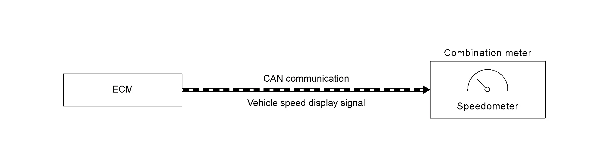
DESCRIPTION
-
The ECM transmits a vehicle speed display signal to the combination meter via CAN communication.
-
The combination meter indicates a Nissan Pathfinder vehicle speed to the speedometer, based on the vehicle speed display signal received from the ECM.
Tachometer
System Description
SYSTEM DIAGRAM

DESCRIPTION
-
ECM converts the pulse signal provided by the crankshaft position sensor to an engine speed signal and transmits it to the combination meter via CAN communication.
-
The combination meter indicates the engine speed to the tachometer according to the engine speed signal received via CAN communication.
Engine Coolant Temperature Gauge
System Description
SYSTEM DIAGRAM
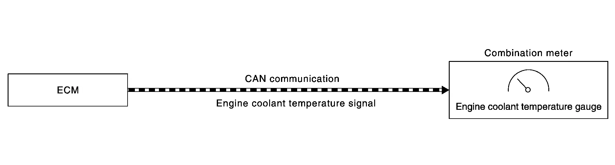
DESCRIPTION
-
ECM reads the engine coolant temperature signal from the engine coolant temperature sensor and transmits the signal to the combination meter via CAN communication.
-
The combination meter indicates the engine coolant temperature to the engine coolant temperature gauge according to the engine coolant temperature signal received via CAN communication.
Fuel Gauge
System Description
SYSTEM DIAGRAM
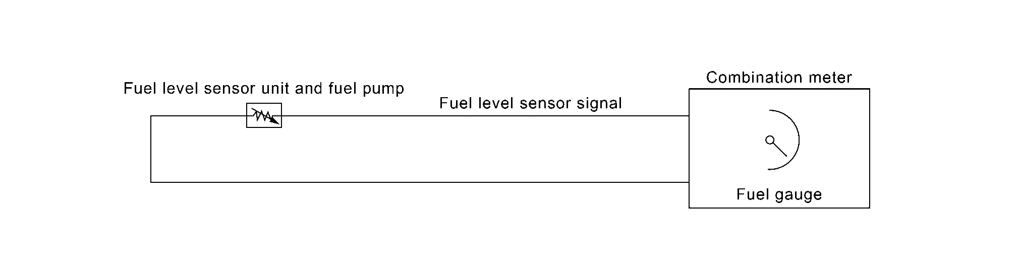
DESCRIPTION
-
The fuel level sensor unit sends a variable resistor signal to the combination meter.
-
The fuel gauge indicates the approximate fuel level in the fuel tank.
Refuel Control
The combination meter accelerates the fuel gauge if the all conditions listed below are met, or the ignition switch changes from OFF to ON.
-
Ignition switch ON.
-
The vehicle is not moving.
-
The fuel level change by approximately 6
 (1 1/2 US gal,1 1/2 Imp gal) or more.
Odometer
System Description
SYSTEM DIAGRAM
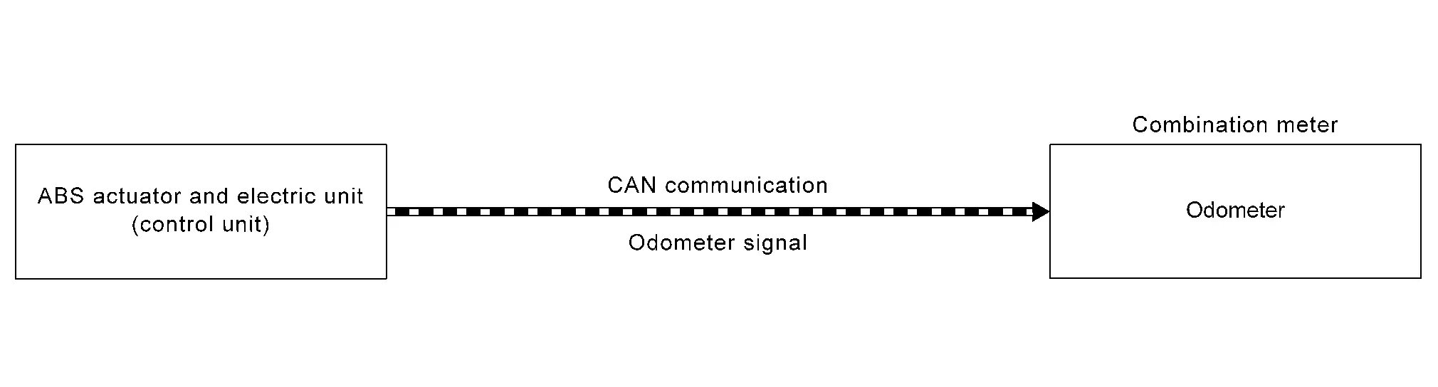
DESCRIPTION
The combination meter calculates mileage, based on the following signals and displays the mileage on the information display.
| Signal name | Signal path |
|---|---|
| Ignition signal | — |
| Odometer signal | ABS actuator and electric unit (control unit)  Combination meter Combination meter |
Distance to Empty
System Description
SYSTEM DIAGRAM
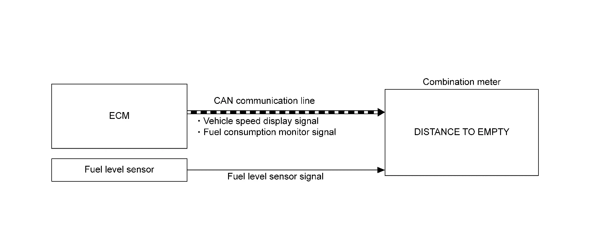
DESCRIPTION
The combination meter calculates distance to empty based on the following signals, and the calculated value is displayed on the information display.
| Signal name | Signal source |
|---|---|
| Ignition signal | — |
| Fuel level sensor signal | Fuel level sensor unit  Combination meter Combination meter |
| Fuel consumption monitor signal | ECM  Combination meter Combination meter |
| Nissan Pathfinder Vehicle speed display signal | ECM  Combination meter Combination meter |
 NOTE:
NOTE:
-
Distance to empty on the information display is updated approximately every 30 seconds.
-
When the ignition switch is turned ON right after battery removal and installation, “−−−” is displayed until after a travel of 30 seconds.
-
The indicated values may not match each other when refueling with the ignition switch ON.
Ambient Temperature
System Description
SYSTEM DIAGRAM
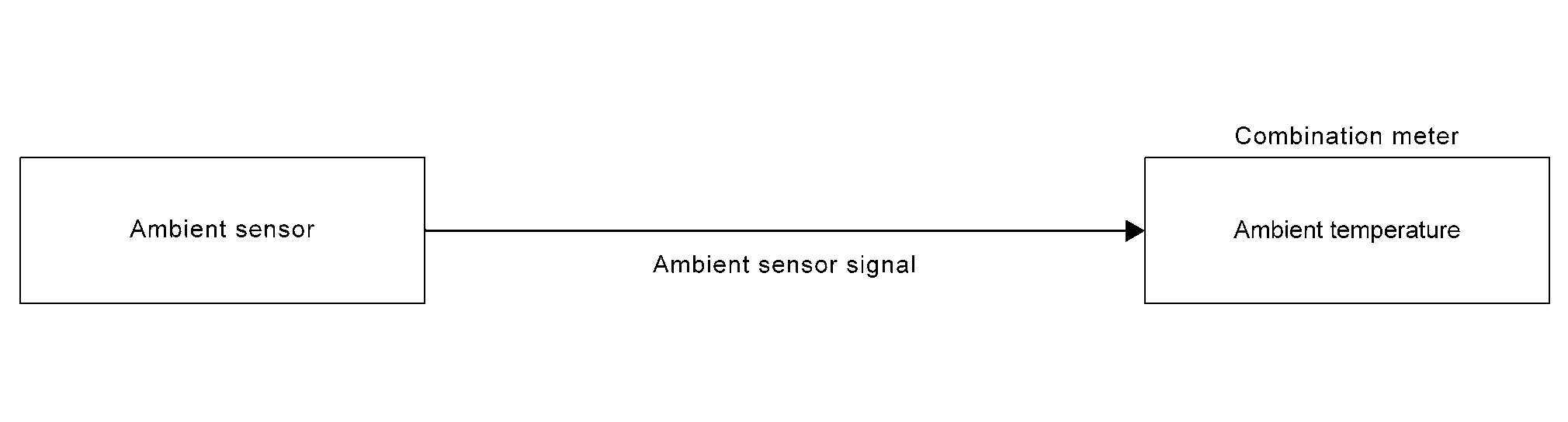
DESCRIPTION
The combination meter calculates ambient temperature based on the following signals, and the calculated value is displayed on the information display.
| Signal name | Signal path |
|---|---|
| Ignition signal | — |
| Ambient sensor signal | Ambient sensor  Combination meter Combination meter |
| Nissan Pathfinder Vehicle speed display signal | ECM  Combination meter Combination meter |
 NOTE:
NOTE:
-
The indicated temperature is corrected based on an ignition signal, ambient temperature detected by the ambient sensor, and Nissan Pathfinder vehicle speed signal. The indicated temperature is not raised under vehicle speed less than 20 km/h (12 MPH).
-
The ambient sensor input value that is displayed on “Data Monitor” of CONSULT is the value before the correction. It may not match the indicated temperature on the information display.
-
Depending on engine heat or heat on the road surfaces, an ambient temperature may be indicated higher than actual one.
Clock
System Description
SYSTEM DIAGRAM
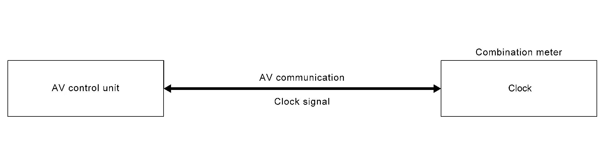
DESCRIPTION
The combination meter calculates time and displays it on the information display.
 NOTE:
NOTE:
The settings screen of the information display allows the selection of time indication between 12-hour and 24-hour formats.
Meter Illumination Control
System Description
SYSTEM DIAGRAM
DESCRIPTION
Back Light Illumination Control Function
The operation of the illumination control switch allows the brightness adjustment of meter illumination.
| Meter illumination | The number of adjustable steps |
|---|---|
| Daytime | 22 step |
| Nighttime | 22 step |
Meter Illumination Control Function
-
Combination meter controls meter illumination, based on the dimmer signal.
-
When ignition is on the combination meter switches mode between Daytime mode and Nighttime mode, according to the following conditions:
Condition Meter illumination Combination switch
(lighting switch)1ST or 2ND position Outdoor: Bright* Daytime mode Outdoor: Dark* Nighttime mode AUTO POSITION Outdoor: Bright* Daytime mode Outdoor: Dark* Nighttime mode Off Daytime mode *: For further information, refer to System Description.
Signal Path
| Signal name | Signal path |
|---|---|
| Ignition signal | — |
| Dimmer signal | BCM  Combination meter Combination meter |
Meter Effect Function
System Description
SYSTEM DIAGRAM
DESCRIPTION
Engine-start Effect Function
When recognizing an engine start, the combination meter controls the following items for producing the effect:
-
Speedometer
-
Tachometer
-
Information display
-
Meter illumination
Meter and Illumination Operations During Engine-start Effect
The combination meter controls the following items during the engine-start effect:
| Control item | Operation | |
|---|---|---|
| Speedometer | Sweeps the pointer. | |
| Tachometer | Sweeps the pointer. | |
| Illumination ring | Increases the brightness to the effect level in stages. | |
| Pointers | Turns on the illumination at the effect level. | |
| Information display | Display the animation. | |
 NOTE:
NOTE:
The pointers are stopped and illumination is turned off while cranking the engine.
Engine Start Judgement
The combination meter judges “engine-start” and activates the engine-start effect only once when the following operational conditions are all satisfied:
| Operational condition | |
|---|---|
| Ignition switch | ON position |
| Nissan Pathfinder Vehicle speed | Less than 1 km/h (0.6 MPH) |
| Engine state | After cranking the engine |
| Information display (SETTING) | The setting of “Welcome Effect” is “On” |
 NOTE:
NOTE:
The engine-start effect exits when any of the above operational conditions is cancelled during the engine-start effect.
Signal Path
The combination meter judges “engine-start”, according to the following signals and activates the engine-start effect function.
| Signal name | Signal source |
|---|---|
| Ignition signal | — |
| Engine status signal | ECM  Combination meter Combination meter |
| Nissan Pathfinder Vehicle speed display signal | ECM  Combination meter Combination meter |
| Starter relay status signal | IPDM E/R  Combination meter Combination meter |
 NOTE:
NOTE:
The engine-start effect function ends if any one of the above conditions is lost during the activation of this function.
Information Display
System Description
SYSTEM DIAGRAM
DESCRIPTION
-
The combination meter receives signals necessary for controlling the operation of the information display from each unit, sensor and switch.
-
The combination meter incorporates a trip computer that displays the warning/information according to the information received from each unit, sensor and switch.
-
The combination meter shows the following functions on the information display:
-
Warning/Indicator
-
Warning confirmation
-
Setting
-
Trip computer
-
Personal display
-
Meter illumination level
-
-
The items displayed in the information display can be selected with the steering switch. Refer to Steering Switch.
WARNING CONFIRMATION
-
The combination meter can interrupt the information display to indicate a warning, based on signals received from each unit and switch.
-
The indicated warning can be checked with “WARNING” during the satisfaction of an interrupt indication condition for each warning.
SETTINGS
The condition of following items can be set:
-
VDC Setting
-
Driver Assistance
-
Personal Display
-
Head-Up Display
-
ECO Mode Setting
-
TPMS Setting
-
Clock
-
Nissan Pathfinder Vehicle Settings
-
Maintenance
-
Customize Display
-
Unit/Language
-
Factory Reset
TRIP COMPUTER
Current Fuel Consumption
The combination meter calculates current fuel consumption based on the following signals, and the calculated value is displayed on the information display:
Current fuel consumption can be compared with average fuel consumption.
| Signal name | Signal source |
|---|---|
| Ignition signal | — |
| Fuel consumption monitor signal | ECM  Combination meter Combination meter |
| Nissan Pathfinder Vehicle speed display signal | ECM  Combination meter Combination meter |
 NOTE:
NOTE:
-
Current fuel consumption on the information display is updated approximately every 0.1 seconds.
-
Current fuel consumption on the information display shows 30 l/100km (0 mpg) when Nissan Pathfinder vehicle speed is 0 km/h (0 MPH).
Average Fuel Consumption
The combination meter calculates average fuel consumption based on the following signals, and the calculated value is displayed on the information display.
| Signal name | Signal source |
|---|---|
| Ignition signal | — |
| Fuel consumption monitor signal | ECM  Combination meter Combination meter |
| Nissan Pathfinder Vehicle speed display signal | ECM  Combination meter Combination meter |
 NOTE:
NOTE:
-
Average fuel consumption on the information display is updated approximately every 30 seconds.
-
Soon after a reset or when the ignition switch is turned ON, “−−−” is displayed until after a travel of 30 seconds and approximately 500 m (0.31 mile).
Current Vehicle Speed
The combination meter calculates current vehicle speed based on the following signals, and the calculated value is displayed on the information display.
| Signal name | Signal path |
|---|---|
| Ignition signal | — |
| Nissan Pathfinder Vehicle speed display signal | ECM  Combination meter Combination meter |
 NOTE:
NOTE:
Current vehicle speed on the information display is updated approximately every 0.3 seconds.
Average Vehicle Speed
The combination meter calculates the average vehicle speed based on the following signals and the calculated value is displayed on the information display.
| Signal name | Signal source |
|---|---|
| Ignition signal | — |
| Nissan Pathfinder Vehicle speed display signal | ECM  Combination meter Combination meter |
 NOTE:
NOTE:
-
Average vehicle speed on the information display is updated approximately every 30 seconds.
-
Soon after a reset, “−−−” is displayed until after 30 seconds.
Travel Time
The combination meter measures and displays travel time (ignition switch ON time).
Travel Distance
The combination meter measures and displays travel distance.
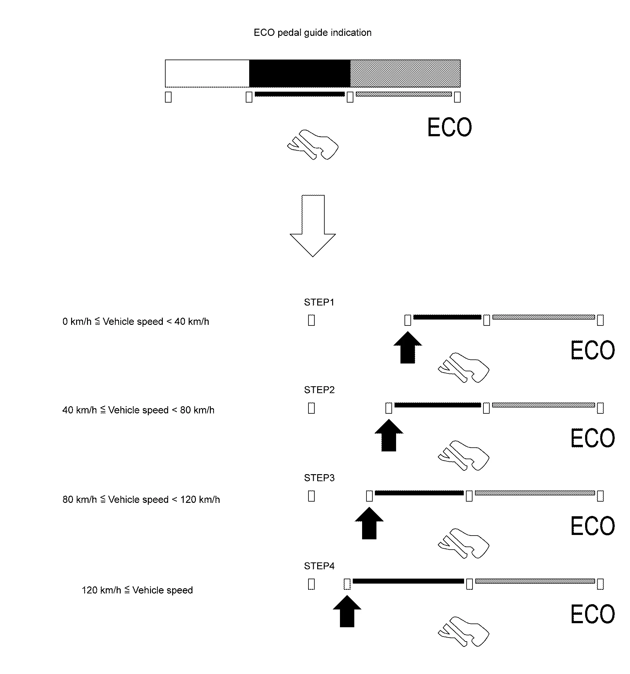
ECO Pedal Guide
The ECO pedal guide consists of Gauge 1  (displays accelerator pedal angle) and Gauge 2
  (displays the guideline of ECO driving).
GAUGE1
-
ECM corrects the accelerator pedal angle to the maximum angle for ECO driving, according to Nissan Pathfinder vehicle speeds.
The maximum accelerator pedal angle increases/decreases as the vehicle speed increases/decreases.
The maximum accelerator angle corrected by ECM is the limitation of ECO driving. The ECO driving is possible only when the number of unlit segments
 of the indicator bar is equal to or less than that of Gauge 2.
The less the number of unlit segments
 of the indicator bar, the more the degree of ECO driving is. And the more the number of unlit segments, the less the degree of ECO driving is.
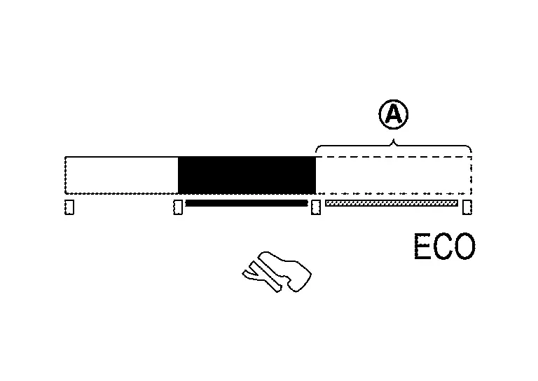
ECM judges the number of lighting segments according to the accelerator pedal angle and Nissan Pathfinder vehicle speed and transmits a CAN communication signal to the combination meter via CAN communication.
The combination meter indicates the number of segments necessary for the ECO pedal guide, according to an ECO pedal guide signal.
 NOTE:
NOTE: The combination meter corrects the number of lighting segments according to a Nissan Pathfinder vehicle speed signal.
GAUGE2
-
The combination meter turns ON/OFF Gauge 2 (guide line for ECO driving) according to a vehicle speed signal.
ECO DRIVE INDICATOR
-
The combination meter displays level of ECO drive in conjunction with ECO pedal guide.
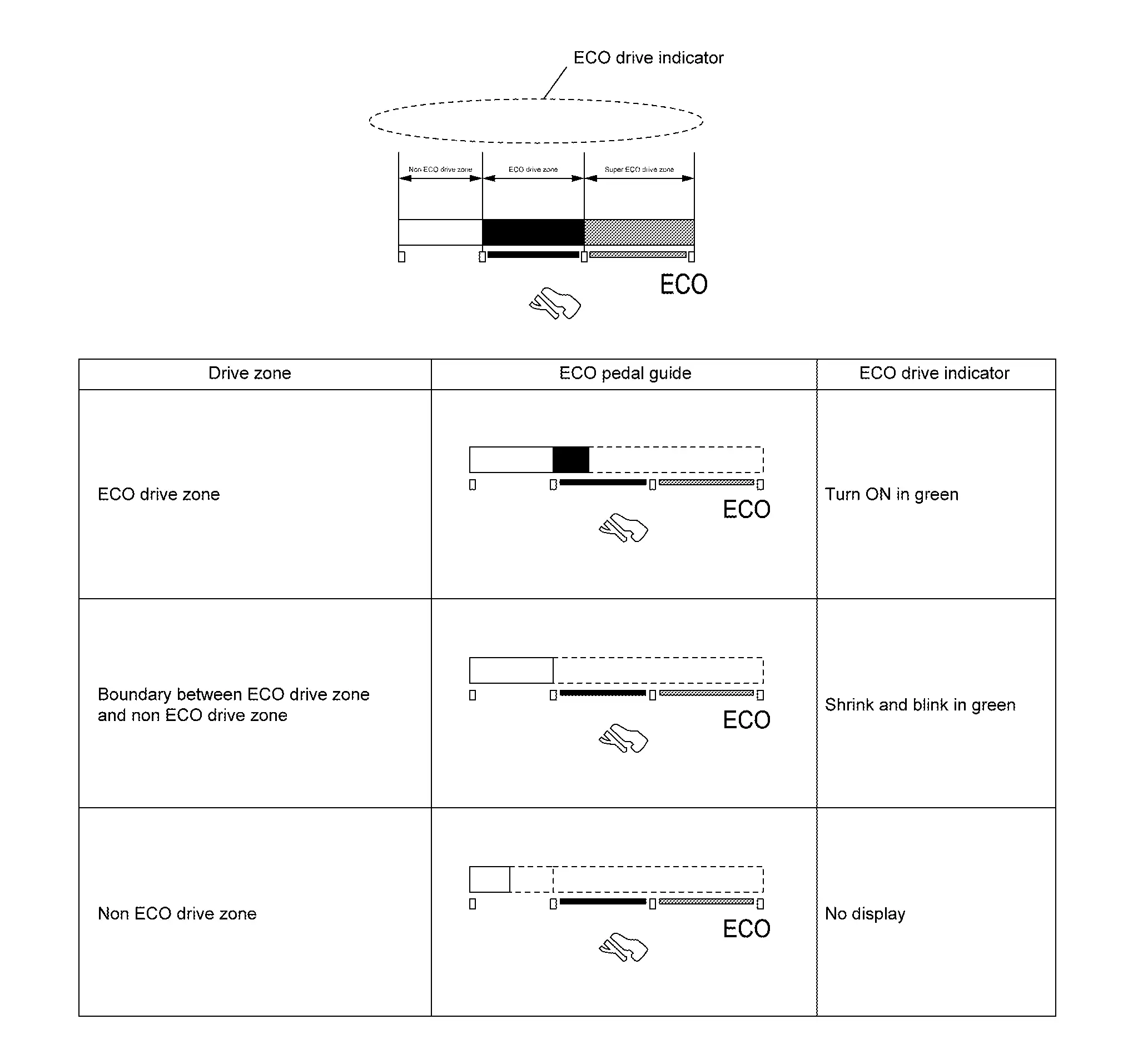
| Signal name | Signal path | |
|---|---|---|
| Ignition signal | — | |
| ECO pedal guide signal | ECM  Combination meter Combination meter |
|
ECO Drive Report
-
The ECO drive report is a function which displays the last drive report of the average fuel consumption, present fuel economy (present value), and the best fuel economy (highest value) on the information display by calculating and recording average fuel consumption.
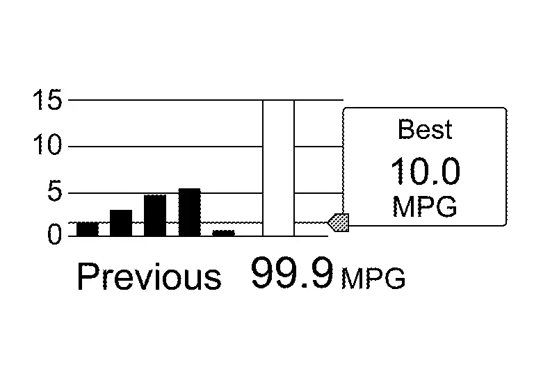
-
The combination meter calculates the average fuel consumption according to the signal below, detects the status of ECO mode , and displays “ECO drive report” on the information display when the ignition switch is turned ON→OFF.
Signal name Signal path Ignition signal — Fuel consumption monitor signal ECM  Combination meter
Nissan Pathfinder Vehicle speed display signal ECM  Combination meter
ECO mode indicator signal ECM  Combination meter
PERSONAL DISPLAY
|
Enhance view
|
Classic view
|
The combination meter can display the various information on the personal display  .
.
The information displayed on the personal display can be selected by the combination meter setting menu.
METER ILLUMINATION LEVEL
The combination meter displays the illuminance level of the back light on the information display by turning the illumination control switch.
Refer to System Description.
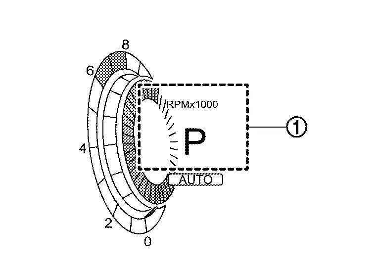
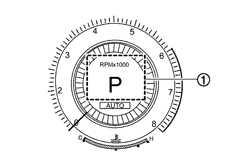
Head up Display
System Description
SYSTEM DIAGRAM
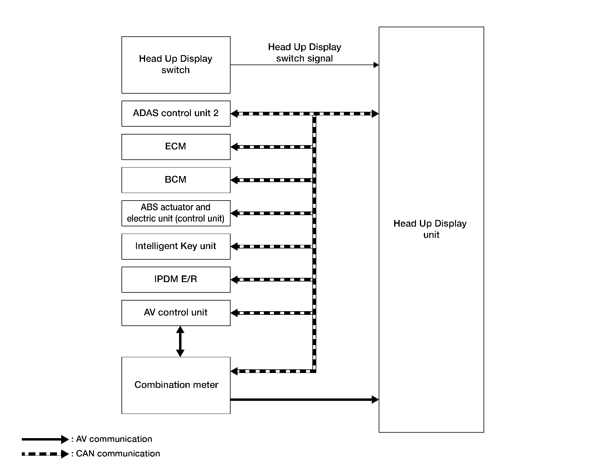
Head Up Display Unit Input Signal (CAN Communication Signal)
| Transmit unit | Signal name |
|---|---|
| ADAS control unit 2 | Display signal |
| ECM | ASCD status signal |
| BCM | Auto ACC status signal |
| Nissan Pathfinder Vehicle status signal | |
| ABS actuator and electric unit (control unit) | Odometer signal |
| Intelligent Key unit | User identification signal |
| IPDM E/R | Battery voltage signal |
| AV control unit | Key link activation status signal |
| Combination meter | Nissan Pathfinder Vehicle speed display signal |
| HUD setting signal |
| Transmit unit | Signal name |
|---|---|
| Combination meter | Navigation signal |
DESCRIPTION
-
The head up display (HUD) displays information on the vehicle speed and the driving assistance system on the windshield glass, and supports safe driving by suppressing the burden due to the movement of the driver's eyes.
-
The head up display unit receives necessary signals from each ECU via CAN communication and local communication.
Operation
-
Ignition switch ON, press the head up display switch to activate head up display.
-
Head up display projects the image on the windshield glass.
-
Image focus on 2.1 m (6.89 ft) from driver's eye point.
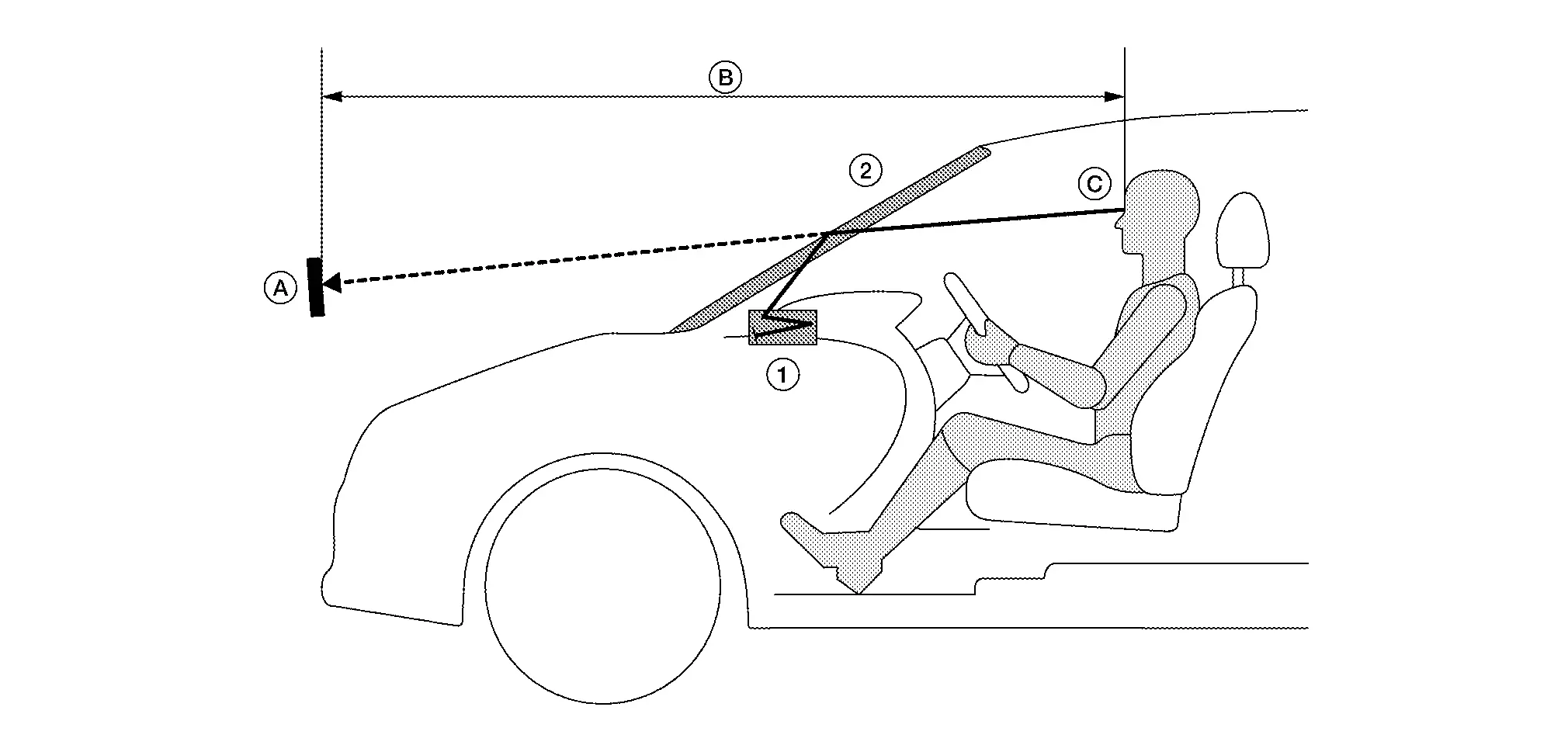
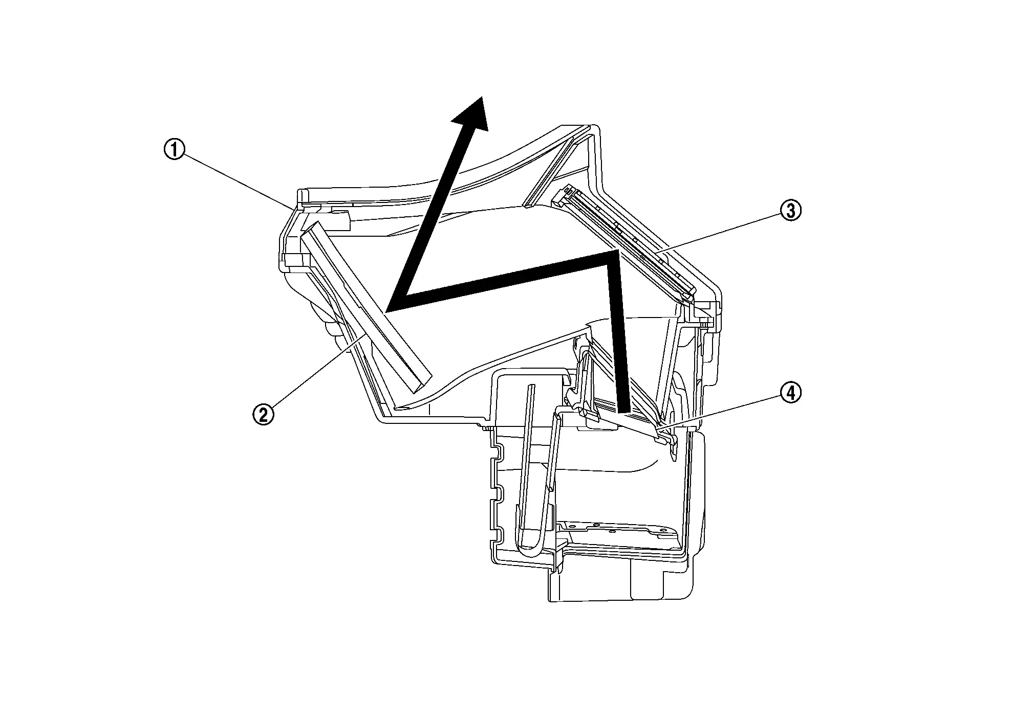
| 1. | Head up display unit | 2. | Windshield glass |
| A. | Virtual image display | B. | 2.1 m (6.89 ft) |
| C. | Eye point |
Structure
The head up display unit projects the image to the windshield glass by reflecting the image of the TFT liquid crystal display on the concave mirror. Also, by manipulating the angle of the concave mirror, the projection position on the windshield glass can be adjusted.
| 1. | Head up display unit | 2. | Concave mirror | 3. | Concave mirror |
| 4. | TFT liquid crystal display | ||||
 |
: Projection path |
Display Item
-
The head up display (HUD) can display one or more of the following features:
-
The head up display unit can cause an interruption on the HUD display to indicate a warning, based on signals received from each unit.
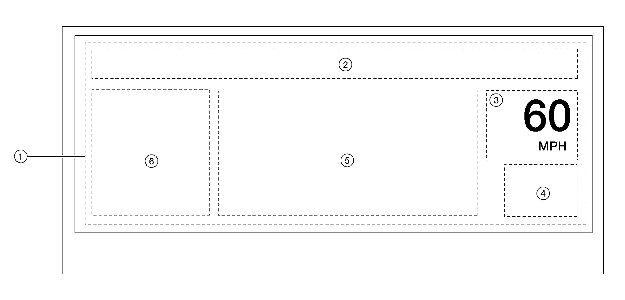
| No. | Display | Description | |
|---|---|---|---|
| 1. | Interrupt display | ProPILOT Assist system warning display | Display ProPILOT Assist system display during ProPILOT Assist system operation |
| AEB warning display | Display AEB warning display during AEB operation | ||
| Turn by Turn display | Display arrows at intersection with navigation guidance and guide traveling direction | ||
| Audio operation display | Display audio operation display during audio switch operation | ||
| 2. | Message display |
|
|
| 3. | Nissan Pathfinder Vehicle speed display | Always display the vehicle speed | |
| 4. | TSR system display | Display TSR system display during TSR system operation | |
| 5. | Driving Aids | ASCD display | Displays setting Nissan Pathfinder vehicle speed during ASCD operation |
| ICC display | Displays information on setting Nissan Pathfinder vehicle speed and presence/absence of preceding vehicle during ICC operation | ||
| ProPILOT Assist system display | Displays setting ProPILOT Assist system status during ProPILOT Assist system operation | ||
| LDW system display | Displays LDW system display during LDW system operation | ||
| I-LI system display | Display I-LI system display during I-LI system operation | ||
| I-FCW system display | Display I-FCW display during I-FCW operation | ||
| 6. | Turn by Turn display | Display arrows at intersection with navigation guidance and guide traveling direction | |
 NOTE:
NOTE:
-
The items displayed depend on vehicle specifications.
-
When placing the ignition switch ON, only Nissan Pathfinder vehicle speed is displayed.
-
Emergency information may display even if the head up display is turned off.
-
The display position, display rotation, display brightness, and display setting adjustment of the head up display can be set on the setting screen of the combination meter. Refer to Switch Name and Function.
Automatic Dimming Function
The head up display unit reads the illuminance sensor value and adjusts the brightness of the display automatically.
 NOTE:
NOTE:
The brightness of the display can be manually adjusted on the combination meter setting screen. Refer to Switch Name and Function.

Nissan Pathfinder (R53) 2022-2026 Service Manual
Contact Us
Nissan Pathfinder Info Center
Email: info@nipathfinder.com
Phone: +1 (800) 123-4567
Address: 123 Pathfinder Blvd, Nashville, TN 37214, USA
Working Hours: Mon–Fri, 9:00 AM – 5:00 PM (EST)
