Nissan Pathfinder: System Description - System ++
Automatic Air Conditioning System
System Description
SYSTEM DIAGRAM
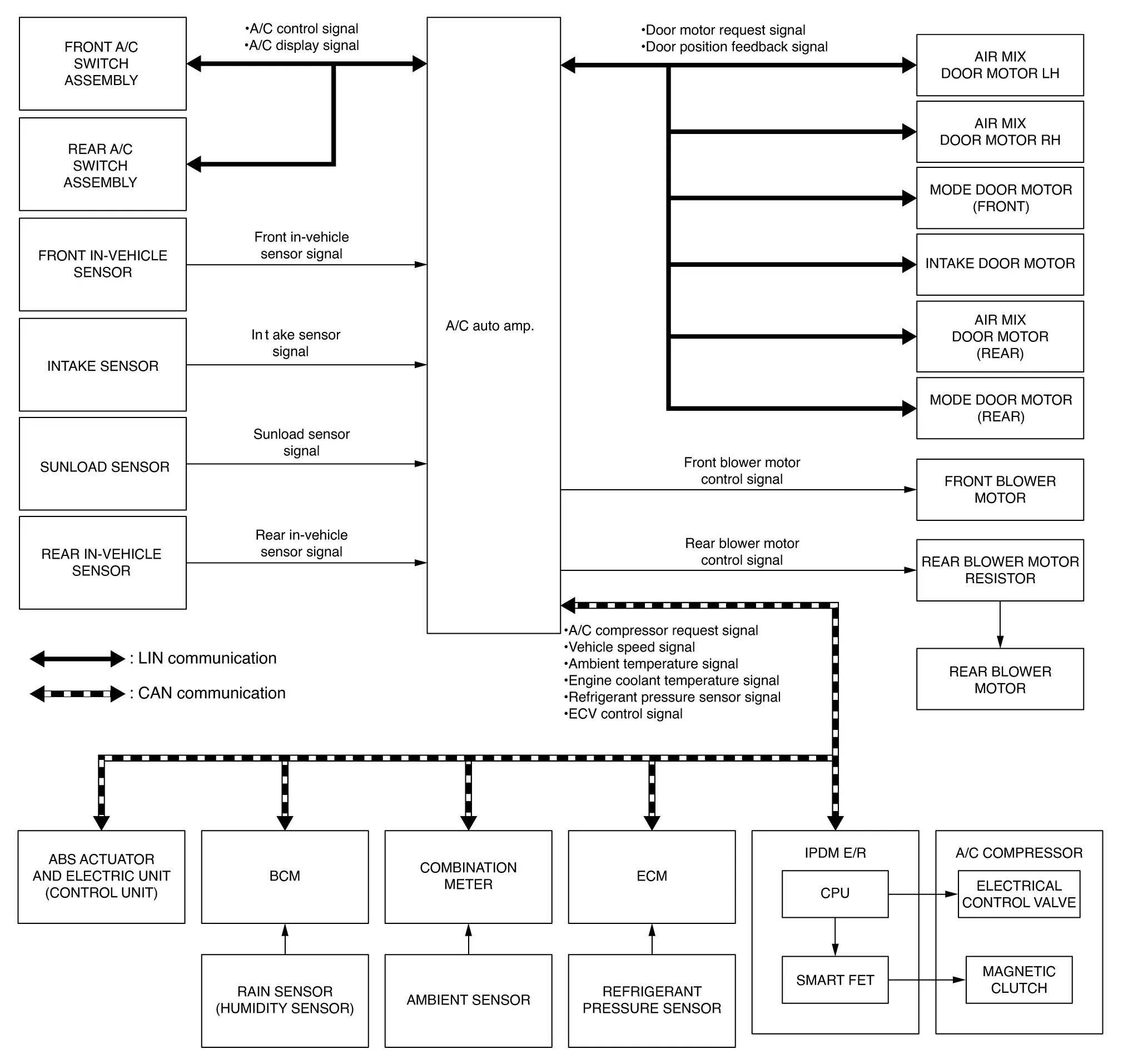
Signal Transmission Function List
| Signal name | Input | Output | Description |
|---|---|---|---|
| Nissan Pathfinder Vehicle speed signal | ABS actuator and electric unit (control unit) | A/C auto amp. (CAN) | Transmits the Nissan Pathfinder vehicle speed signal to A/C auto amp. via CAN communication. |
| Remote engine start status signal | BCM | Transmits the remote engine start status signal to A/C auto amp. via CAN communication. | |
| Humidity level signal | Transmits the humidity level signal to A/C auto amp. via CAN communication. | ||
| Ambient temperature signal | Combination meter | Transmits the ambient temperature signal to A/C auto amp. via CAN communication. | |
| Engine coolant temperature signal | ECM | Transmits the engine coolant temperature signal to A/C auto amp. via CAN communication. | |
| Refrigerant pressure sensor signal | Transmits the refrigerant pressor sensor signal to A/C auto amp. via CAN communication. | ||
| A/C compressor request signal | IPDM E/R (CAN) | Transmits the A/C compressor request signal to IPDM E/R via CAN communication. | |
| A/C ON signal | A/C auto amp. | ECM (CAN) | Receives mainly the A/C ON signal from A/C auto amp. via CAN communication. |
| Blower fan ON signal | Receives mainly the blower fan ON signal from A/C auto amp. via CAN communication. | ||
| Cooling fan request signal | Receives mainly the cooling fan request signal from A/C auto amp. via CAN communication. | ||
| ECV control signal | IPDM E/R (CAN) | Receives mainly the ECV control signal from A/C auto amp. via CAN communication. | |
| A/C control signal | Front A/C switch assembly | A/C auto amp. (LIN) | Transmits the A/C control signal to A/C auto amp. via LIN communication. |
| A/C display signal | A/C auto amp. | Front A/C switch assembly (LIN) | Receives mainly the A/C display signal from A/C auto amp. via LIN communication. |
| Rear A/C control signal | Rear A/C switch assembly* | A/C auto amp. (LIN) | Transmits the rear A/C control signal ti A/C auto amp. via LIN communication. |
| Rear A/C display signal | A/C auto amp. | Rear A/C switch assembly* (LIN) | Receives mainly the rear A/C display signal from A/C auto amp. via LIN communication. |
| Door position feedback signal | Air mix door motor LH | A/C auto amp. (LIN) | Transmits the door position feedback signal to A/C auto amp. via LIN communication. |
| Air mix door motor RH | |||
| Air mix door motor (rear)* | |||
| Intake door motor | |||
| Mode door motor (front) | |||
| Mode door motor (rear)* | |||
| Door motor request signal | A/C auto amp. | Air mix door motor LH (LIN) | Receives mainly the door motor request signal from A/C auto amp. via LIN communication. |
| Air mix door motor RH (LIN) | |||
| Air mix door motor (rear)* (LIN) | |||
| Intake door motor (LIN) | |||
| Mode door motor (front) (LIN) | |||
| Mode door motor (rear)* (LIN) |
*: With rear air control
DESCRIPTION
-
Air conditioning system is controlled by each function of A/C auto amp., ECM and IPDM E/R.
-
Each operation of air conditioning system can be controlled by the front, and rear, A/C switch assembly.
CONTROL BY A/C auto amp.
-
Temperature Control
-
Air Outlet Control
-
Air Inlet Control
-
Door Control
-
Air Flow Control
-
A/C Compressor Control
-
Cooling Fan Operation Request Control
-
Remote Engine Start Control
CORRECTION FOR INPUT VALUE
-
Ambient temperature correction
-
A/C auto amp. inputs the temperature detected by ambient temperature signal received from combination meter via CAN communication as the ambient temperature.
-
A/C auto amp. performs the correction of the temperature detected by ambient sensor for air conditioning control.
-
A/C auto amp. selects and uses the initial value of ambient temperature data depending on the engine coolant temperature when placing the ignition switch from OFF to ON. The detection temperature of the ambient sensor is used when engine coolant temperature is low [less than approximately 133°F (56°C)]. The memory data (before the ignition switch is OFF) when the engine is warmed up [approximately 133°F (56°C) or more].
-
The correction of the ambient temperature is not performed when the detection temperature of the ambient temperature is less than approximately –4°F (−20°C).
-
-
In-Nissan Pathfinder vehicle temperature correction
-
A/C auto amp. inputs the temperature detected by in-vehicle sensors as the in-Nissan Pathfinder vehicle temperature.
-
A/C auto amp. performs the correction of the temperature detected by in-Nissan Pathfinder vehicle sensors for air conditioning control.
-
A/C auto amp. performs the correction so that the recognition passenger room temperature changes depending on the difference between the detected passenger room temperature and the recognition passenger room temperature. If the difference is large, the changing is early. The changing becomes slow as the difference becomes small.
-
-
Intake temperature correction
-
A/C auto amp. inputs the temperature detected by intake sensor as the intake temperature (evaporator temperature).
-
A/C auto amp. performs the correction of the temperature detected by intake sensor for air conditioning control.
-
A/C auto amp. performs the correction so that the recognition intake temperature changes depending on the difference between the detected intake temperature and the recognition intake temperature. If the difference is large, the changing is early. The changing becomes slow as the difference becomes small.
-
-
Sunload amount correction
-
A/C auto amp. inputs the sunload amount detected by sunload sensor.
-
A/C auto amp. performs the correction of the sunload amount detected by sunload sensor for air conditioning control.
-
When the sunload amount suddenly changes, for example when entering a tunnel, perform the correction so that the recognition sunload amount of the A/C auto amp. changes slowly.
-
-
Set temperature correction
-
A/C auto amp. performs the correction to the target temperature set by the A/C switch assembly so as to match the temperature felt by the passengers depending on the ambient temperature detected by ambient sensor and controls it so that the in-Nissan Pathfinder vehicle temperature is always the most suitable.
-
CONTROL BY ECM
A/C Compressor Control
CONTROL BY IPDM E/R
A/C Compressor Control
Air Flow Control
DESCRIPTION
-
A/C auto amp. changes duty ratio of blower motor drive signal and controls air flow continuously. When air flow is increased, duty ratio of front blower motor control signal gradually increases to prevent a sudden increase in air flow.
-
In addition to manual control and automatic control, air flow control consists of starting fan speed control, low coolant temperature starting control, high in-Nissan Pathfinder vehicle temperature starting control and fan speed control at door motor operation.
AUTOMATIC AIR FLOW CONTROL
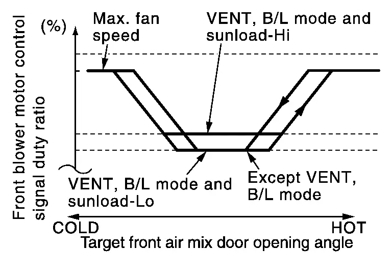
-
A/C auto amp. decides target air flow depending on target air mix door (front) opening angle.
-
A/C auto amp. changes duty ratio of front blower motor control signal and controls the air flow continuously so that air flow matches the target air flow.
-
When air outlet is VENT or B/L, the minimum air flow is changed depending on sunload.
STARTING AIR FLOW CONTROL
-
When front blower motor is activated, A/C auto amp. gradually increases duty ratio of front blower motor control signal to prevent a sudden increase in discharge air flow.
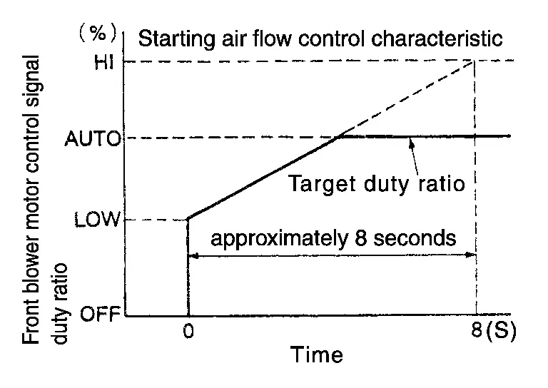
-
It takes approximately 8 seconds for air flow to reach HI from LOW.
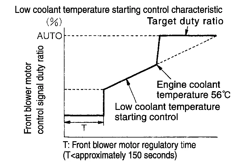
LOW COOLANT TEMPERATURE STARTING CONTROL
If the engine coolant temperature is 133°F (56°C) or less, to prevent a cold discharged air flow, A/C auto amp. suspends front blower motor activation for the maximum 150 seconds depending on target air mix door (front) opening angle. After this, front blower motor control signal is increased gradually, and front blower motor is activated.
HIGH IN-VEHICLE TEMPERATURE STARTING CONTROL
When front evaporator fin temperature is high [intake sensor value is 95°F (35°C) or more], to prevent a hot discharged air flow, A/C auto amp. suspends front blower motor activation for approximately 3 seconds so that front evaporator is cooled by refrigerant.
FAN SPEED CONTROL AT DOOR MOTOR OPERATION
When mode door motor (front) is activated while air flow is more than the specified value, A/C auto amp. reduces fan speed temporarily so that mode door (front) moves smoothly.
Air Inlet Control
The intake door is automatically controlled by the temperature setting, ambient temperature, in-vehicle temperature, intake temperature, amount of sunload and ON/OFF operation of the compressor.
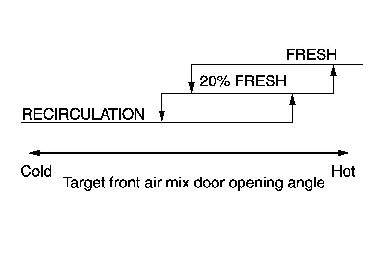
Intake door automatic control selects FRE, 20% FRE, or REC depending on a target air mix door (front) opening angle, based on in-Nissan Pathfinder vehicle temperature, ambient temperature, and sunload.
Air Outlet Control
-
While air outlet is in automatic control, A/C auto amp. selects the mode door (front) position depending on a target air mix door (front) angle and outlet air temperature calculated from sunload.
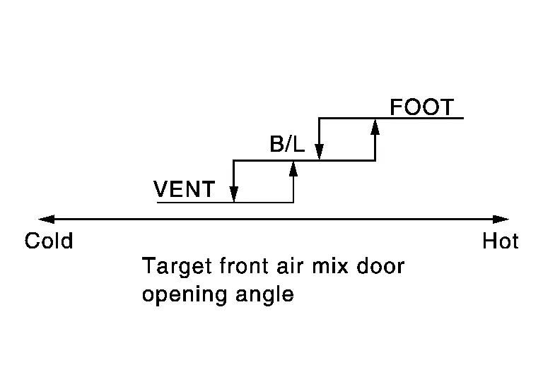
-
If ambient temperature is excessively low, D/F is selected to prevent windshield fogging when air outlet is set to FOOT.
Compressor Control
DESCRIPTION
-
When the compressor activation condition is satisfied while blower motor is activated, A/C auto amp. transmits A/C ON signal and blower fan ON signal to ECM via CAN communication.
-
ECM judges that the compressor can be activated depending on each sensors state (refrigerant pressure sensor signal and others) and transmits A/C compressor request signal to IPDM E/R via CAN communication.
-
IPDM E/R turns smart FET ON and activates the compressor depending on request from ECM.
COMPRESSOR PROTECTION CONTROL AT PRESSURE MALFUNCTION
When high-pressure side value that is detected by refrigerant pressure sensor is as per the following state, ECM requests IPDM E/R to turn smart FET OFF and stops the compressor:
-
3.12 MPa (31.82 kg/cm2, 452.4 psi) or more (When the engine speed is less than 1,500 rpm)
-
2.74 MPa (27.95 kg/cm2, 397.3 psi) or more (When the engine speed is 1,500 rpm or more)
-
0.14 MPa (1.43 kg/cm2, 20.3 psi) or less
COMPRESSOR OIL CIRCULATION CONTROL
When the engine starts while the engine coolant temperature is 133°F (56°C) or less, ECM activates the compressor for approximately 6 seconds and circulates the compressor lubricant once.
LOW TEMPERATURE PROTECTION CONTROL
-
When intake sensor detects that front evaporator fin temperature is 37°F (2.5°C) or less, A/C auto amp. requests ECM to turn compressor OFF, and stops the compressor.
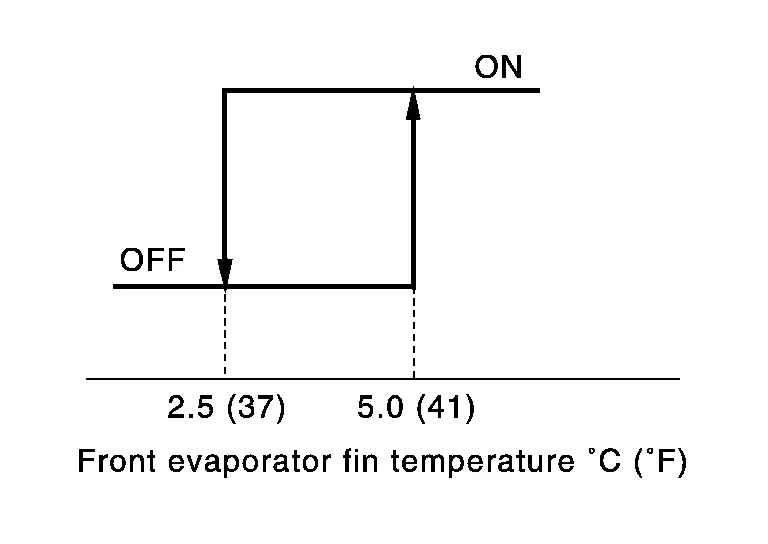
-
When the front evaporator fin temperature returns to 41°F (5.0°C) or more, the compressor is activated.
OPERATING RATE CONTROL
When set temperature is other than fully cold or air outlet is “VENT”, “B/L” or “FOOT” A/C auto amp. controls the compressor activation depending on ambient temperature.
AIR CONDITIONING CUT CONTROL
When set engine is running is excessively high load condition, ECM requests IPDM E/R to turn smart FET OFF, and stops the compressor. Refer to System Description for details.
Door Control
DOOR MOTOR CONTROL
-
LCU (Local Control Unit) is built into each door motor, and detects door position by PBR (Potentio Balance Resistor).
-
A/C auto amp. communicates with each LCU via communication line and receives each door position feedback signal from each LCU.
-
Each LCU controls each door to the appropriate position depending on the control signal from A/C auto amp.
-
Each LCU transmits the signal of door movement completion to A/C auto amp., when the door movement is completed.
SWITCH AND THEIR CONTROL FUNCTION
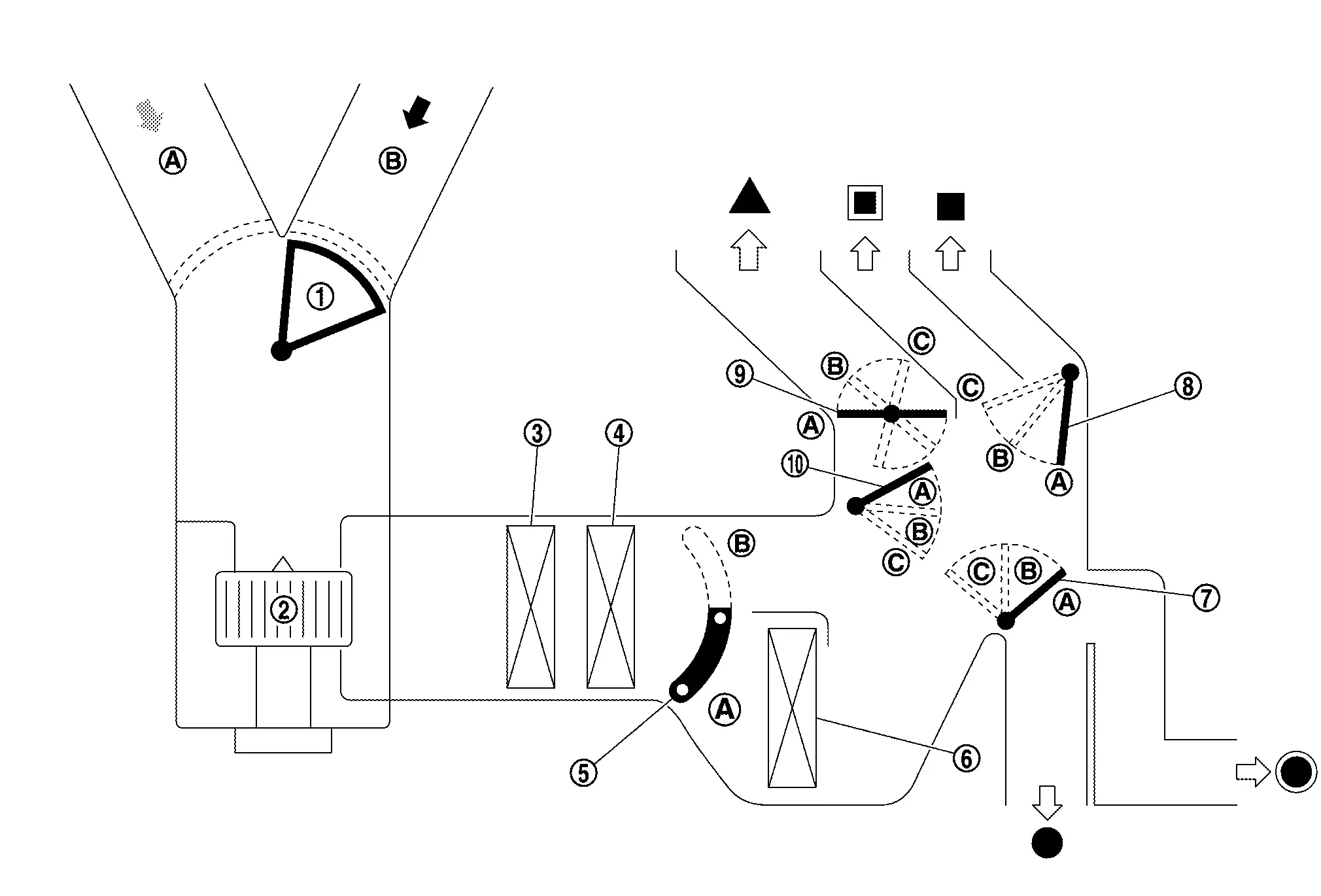
| 1. | Intake door | 2. | Front blower motor | 3. | In-cabin microfilter |
| 4. | Front evaporator | 5. | Air mix door (front) | 6. | Front heater core |
| 7. | Foot door | 8. | Ventilator door | 9. | Defroster door |
| 10. | Max. cool door | ||||
 |
Fresh air |  |
Recirculation air |  |
Discharge air |
 |
Defroster |  |
Center ventilator |  |
Side ventilator |
 |
Front foot |  |
Rear foot | ||
| Switch position | Door position | |||||||||
|---|---|---|---|---|---|---|---|---|---|---|
| Mode door (front) | Intake door | Air mix door (front) | ||||||||
| Ventilator door | Max. cool door | Defroster door | Foot door | (Driver side) | (Passenger side) | |||||
| AUTO switch |  |
AUTO | ||||||||
| MODE switch |  |
A | A | A | A | — | — | — | ||
 |
B | B | A | B | ||||||
 |
C | C | B | B | ||||||
 |
C | B | B | B | ||||||
| DEF switch |  |
 |
C | A | C | C | ||||
| Intake switch* |  |
 |
— | — | — | — | A | |||
 |
B | |||||||||
| Temperature control switch (Driver side) | SYNC switch: ON |
Full cold [60°F or 61°F (18°C)] |
— | A | ||||||
|
62°F – 88°F (18.5°C – 31.5°C) |
AUTO | |||||||||
|
Full hot [89°F or 90°F (32°C)] |
B | |||||||||
| Temperature control switch (Driver side) | SYNC switch: OFF |
Full cold [60°F or 61°F (18°C)] |
A | — | ||||||
|
62°F – 88°F (18.5°C – 31.5°C) |
AUTO | |||||||||
|
Full hot [89°F or 90°F (32°C)] |
B | |||||||||
| Temperature control switch (Passenger side) |
Full cold [60°F or 61°F (18°C)] |
— | A | |||||||
|
62°F – 88°F (18.5°C – 31.5°C) |
AUTO | |||||||||
|
Full hot [89°F or 90°F (32°C)] |
B | |||||||||
| ON·OFF switch | OFF | C | C | B | B | B | — | |||
*: Inlet status is displayed by indicator during activating automatic control
AIR DISTRIBUTION
| Discharge air flow | ||||||
|---|---|---|---|---|---|---|
| MODE/DEF set position | Condition | Air outlet/distribution | ||||
| Ventilator | Foot | Defroster | ||||
| Center | Side | Front | Rear | |||
 |
SYNC switch: ON | 50% | 50% | — | — | |
 |
26% | 30% | 30% | 14% | — | |
 |
— | 14% | 40% | 16.5% | 29.5% | |
 |
— | 14% | 35% | 16% | 35% | |
 |
— | 12% | — | 88% | ||
Temperature Control
-
When ignition switch is in the ON position, A/C auto amp. always automatically controls temperature regardless of front air conditioning operational state.
-
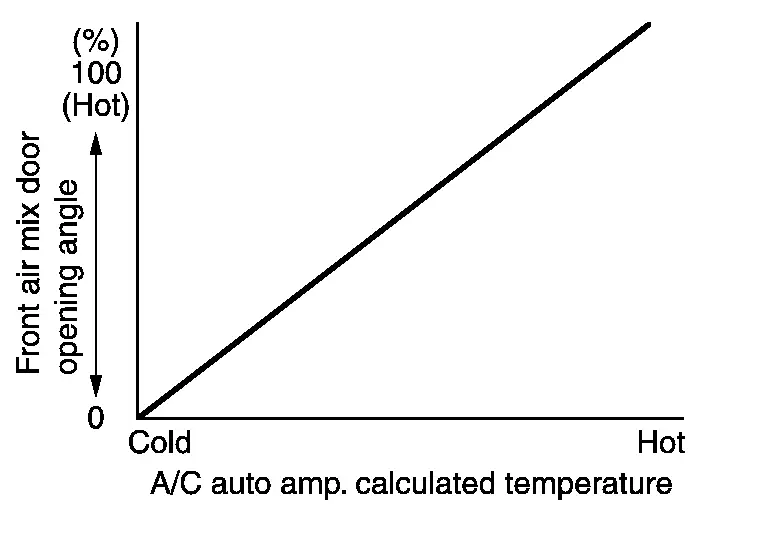
A/C auto amp. calculates the target air mix door (front) opening angle depending on set temperature, in-Nissan Pathfinder vehicle temperature, ambient temperature, and sunload.
-
Air mix door (front) is controlled depending on the comparison of current air mix door (front) opening angle and target air mix door (front) opening angle.
-
Regardless of in-Nissan Pathfinder vehicle temperature, ambient temperature, and sunload, air mix door (front) is fixed at the fully cold position when set temperature is 18.0°C (60°F or 61°F), and at the fully hot position when set temperature is 32.0°C (89°F or 90°F).
Cooling Fan Operation Request Control
DESCRIPTION
A/C auto amp. controls the cooling fan operation request according to the refrigerant pressure status and Nissan Pathfinder vehicle speed status.
 NOTE:
NOTE:
For an overview of the cooling fan and information about control. Refer to System Description.
CONTROL OUTLINE
-
A/C auto amp. receives the refrigerant pressure sensor signal from ECM via CAN communication and Nissan Pathfinder vehicle speed signal from the ABS actuator and electric unit (control unit) via CAN communication.
-
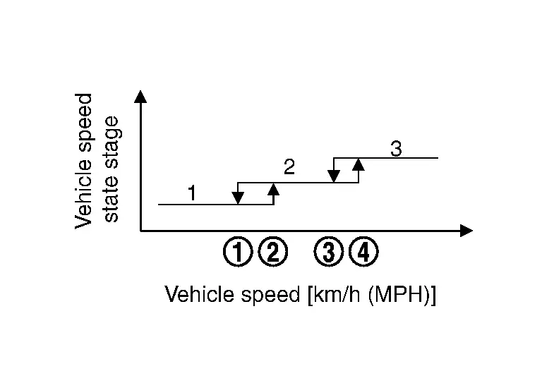
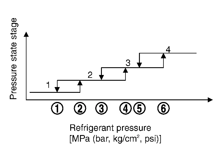
A/C auto amp. sets one of the optionally determined stages according to the received refrigerant pressure sensor signal and Nissan Pathfinder vehicle speed signal.
 NOTE:
NOTE: For the rules that prescribe the predetermined stages, refer to the following figures:
-
Nissan Pathfinder Vehicle speed stages
Vehicle speed [km/h (MPH)]
-
 : 12 (7.5)
 -
 : 20 (12)
 -
 : 72 (45)
 -
 : 80 (50)
-
-
Refrigerant pressure stages
Refrigerant pressure [MPa (bar, kg/cm2, psi)]
-
 : 1.28 (12.8, 13.1, 186)
 -
 : 1.28 (12.8, 13.1, 186)
 -
 : 1.28 (12.8, 13.1, 186)
 -
 : 1.28 (12.8, 13.1, 186)
 -
 : 1.28 (12.8, 13.1, 186)
 -
 : 1.58 (15.8, 16.1, 229)
-
-
-
The requested cooling fan operation strength (0%, 40%, 100%) is determined according to the combination of these two stages, and the request signal is transmitted to ECM via CAN communication.
Remote Engine Start Control
A/C auto amp. operates air conditioning system in following mode according to the vehicle situation when remote engine start function is operated. For an overall description of the remote engine start function. Refer to System Description.
| Conditions | Cooler mode | Normal mode | Defrost mode | Heated normal mode | |
|---|---|---|---|---|---|
| Nissan Pathfinder Vehicle situation |
Air mix door opening angle*1 (COLD ⇔ HOT) |
When XM*2 is changed while defrost mode | |||
| Air conditioning control | Air flow | AUTO | AUTO | AUTO | AUTO |
| Air outlet | AUTO | AUTO | DEF | AUTO | |
| Air inlet | AUTO | AUTO | AUTO | AUTO | |
| A/C compressor | ON | Depend on A/C request | Depend on A/C request | Depend on A/C request | |
| Setting temperature (driver side) | 77°F (25°C) | 77°F (25°C) | 77°F (25°C) | 77°F (25°C) | |
| Setting temperature (passenger side) | 77°F (25°C) | 77°F (25°C) | 77°F (25°C) | 77°F (25°C) | |
| Setting temperature (rear) | 77°F (25°C) | 77°F (25°C) | 77°F (25°C) | 77°F (25°C) | |
| SYNC | ON | ON | ON | ON | |
| Other control | Heated steering wheel control | OFF | OFF | ON | No change |
| Heated seat control | OFF | OFF | AUTO | No change | |
| Rear window defogger control | OFF | OFF | ON | No change | |
| Front A/C switch assembly | Switch indicator lamp / Display | OFF | OFF | OFF | OFF |
| Switch operation | Not accepted | Not accepted | Not accepted | Not accepted | |
*1: For details of air mix door opening angle. Refer to Temperature Control.
*2: The reading of XM can be checked by the data monitor of CONSULT.
Remote engine start control OFF condition (When any of the following conditions are satisfied)
-
Remote engine start function: Stop
-
Ignition switch: OFF

Nissan Pathfinder (R53) 2022-2026 Service Manual
Contact Us
Nissan Pathfinder Info Center
Email: info@nipathfinder.com
Phone: +1 (800) 123-4567
Address: 123 Pathfinder Blvd, Nashville, TN 37214, USA
Working Hours: Mon–Fri, 9:00 AM – 5:00 PM (EST)
