Nissan Pathfinder: Heater & Air Conditioning System - Heating and Cooling Unit Assembly
- Front Heating and Cooling Unit Assembly
- Rear Heating and Cooling Unit Assembly
- Front Heater Core
- Rear Heater Core
- Front Evaporator
- Rear Evaporator
- Front Expansion Valve
- Rear Expansion Valve
Front Heating and Cooling Unit Assembly Nissan Pathfinder SUV
Exploded View
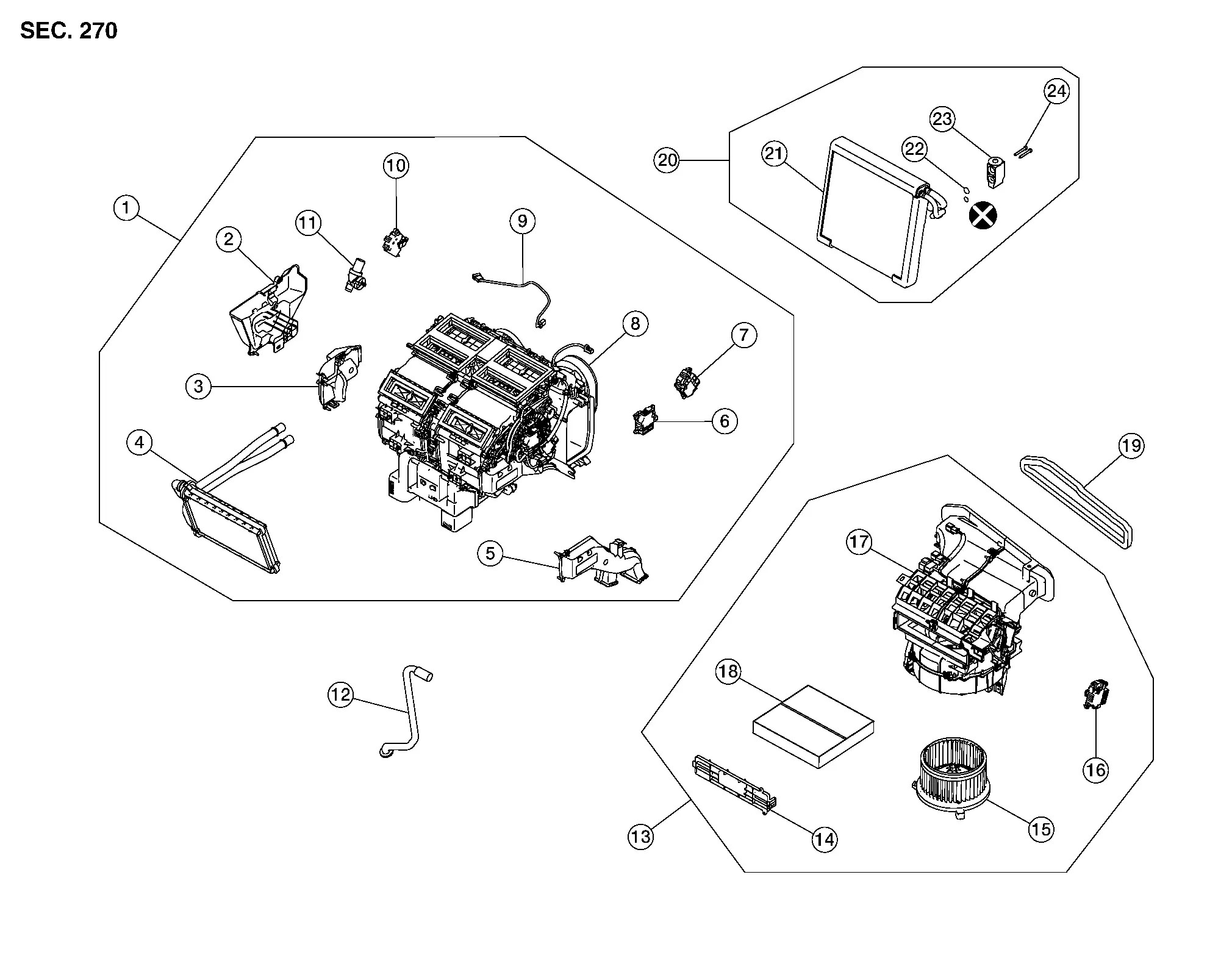
Front Heating and Cooling Unit Assembly Components

| 1. | Front heating and cooling unit assembly | 2. | Front heater core pipes cover | 3. | Foot duct (LH) |
| 4. | Front heater core | 5. | Foot duct (RH) | 6. | Mode door motor (front) |
| 7. | Air mix door motor (RH) | 8. | Expansion valve grommet | 9. | Intake sensor |
| 10. | Air mix door motor (LH) | 11. | Aspirator hose | 12. | Drain hose |
| 13. | Front blower unit assembly | 14. | In-cabin microfilter cover | 15. | Front blower motor |
| 16. | Intake door motor | 17. | Front blower unit | 18. | In-cabin microfilter |
| 19. | Blower motor intake packing | 20. | Front evaporator assembly | 21. | Front evaporator |
| 22. | O-rings | 23. | Front expansion valve | 24. | Front evaporator bolts |
Removal and Installation
REMOVAL
Remove steering member assembly. Refer to Removal and Installation.
Remove bolts retaining front heating and cooling unit assembly to steering member. Refer to Exploded View.
Separate front heating and cooling unit assembly from steering member.
INSTALLATION
Installation is in the reverse order of removal.
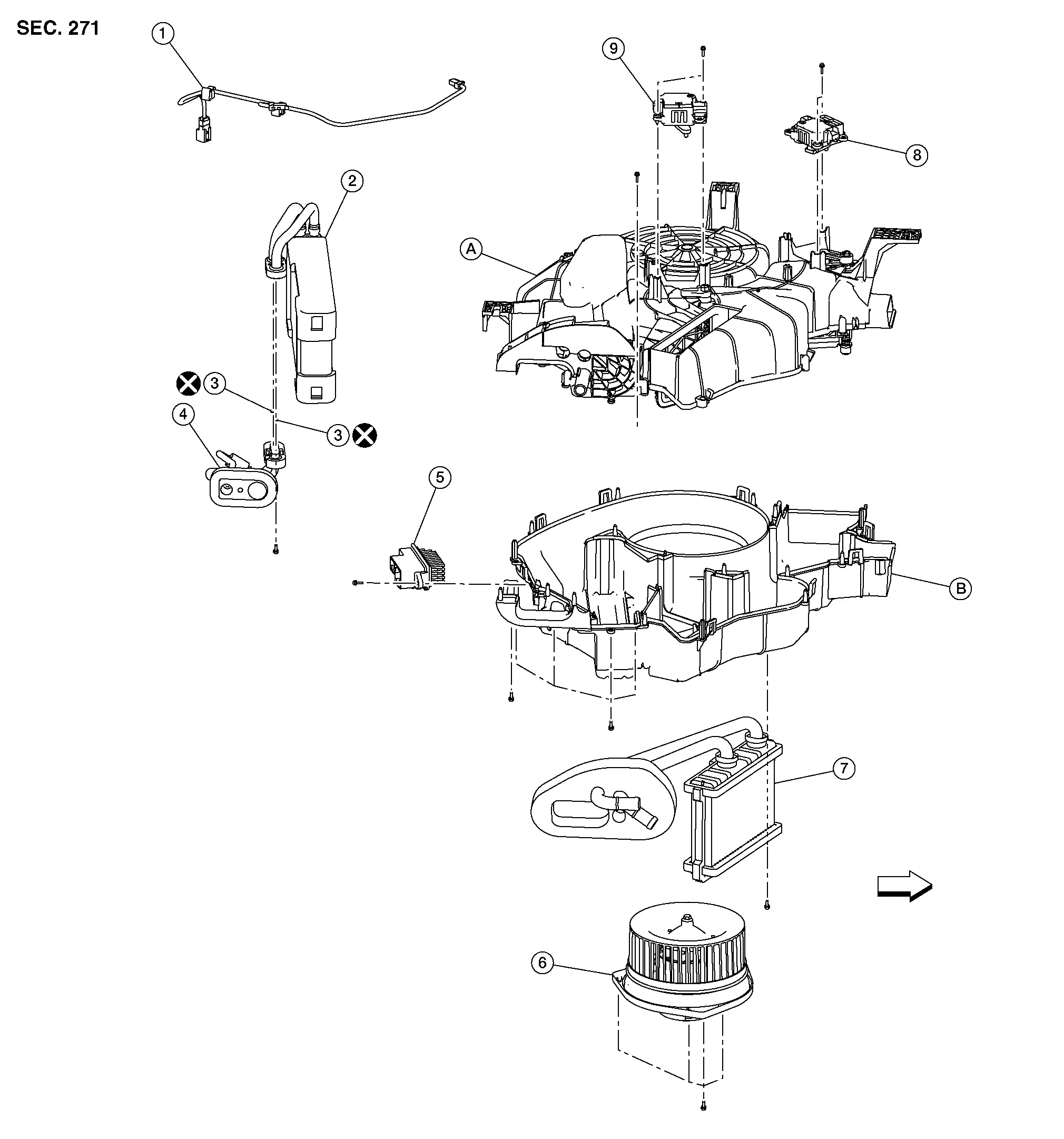
Rear Heating and Cooling Unit Assembly Nissan Pathfinder 2026
Exploded View

| 1. | Intake sensor | 2. | Rear evaporator | 3. | O-ring |
| 4. | Rear expansion valve | 5. | Rear blower motor resistor | 6. | Rear blower motor |
| 7. | Rear heater core | 8. | Mode door motor (rear) | 9. | Air mix door motor (rear) |
| A. | Rear heating and cooling unit upper housing | B. | Rear heating and cooling unit lower housing |
 |
Front |
Removal and Installation
REMOVAL
Discharge refrigerant. Refer to Recycle Refrigerant.
Drain engine coolant. Refer to Draining.
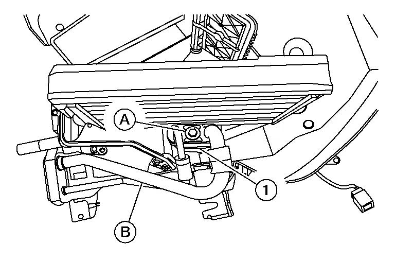
Remove clips (A), then disconnect heater hoses (B) from rear heating and cooling unit assembly.
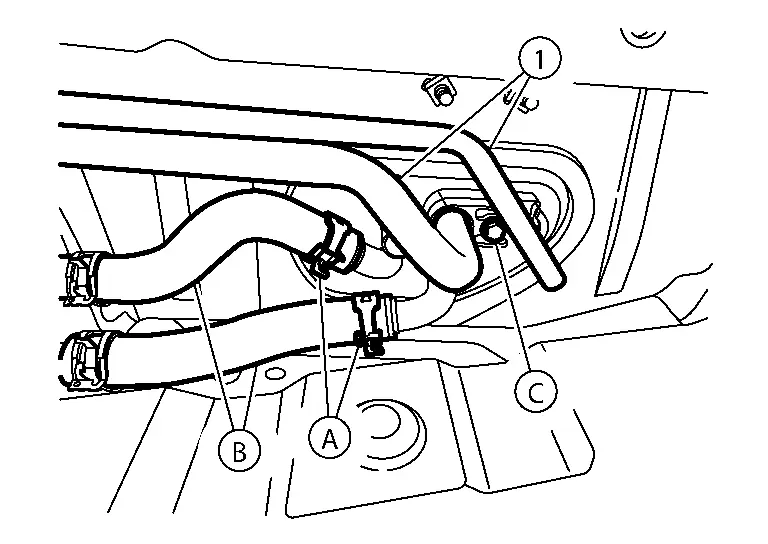
| (1) | : Underfloor rear high-pressure and low-pressure A/C pipes |
| (C) | : Bolt |
Remove bolt (C), then disconnect underfloor rear high-pressure and low-pressure pipes (1) from rear expansion valve pipe assembly.

CAUTION:
Cap or wrap the joint of the pipe with suitable material such as vinyl tape to avoid the entry of air.
| (A) | : Clips |
| (B) | : Rear heater hoses |
Remove back door kicking plate. Refer to Removal and Installation.
Remove luggage side lower finisher (RH). Refer to Removal and Installation.
Remove jack bracket bolts, then remove jack bracket.
Remove storage box side finisher bracket, then remove storage box side finisher. Refer to Removal and Installation.
Disconnect harness connectors from rear heating and cooling unit assembly.
Remove nuts (A) retaining rear heating and cooling unit assembly to Nissan Pathfinder vehicle body, then remove luggage floor bracket (B).
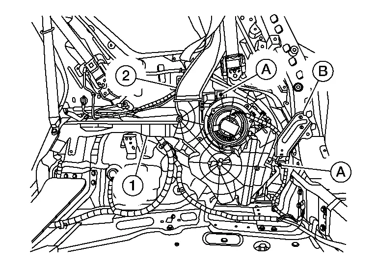
Remove rear ventilator connecting duct (2). Refer to Removal and Installation.
Remove rear ventilator duct lower (1). Refer to Removal and Installation.
Remove rear heating and cooling unit assembly bolts.
Disconnect drain hose from rear heating and cooling unit assembly.
Remove rear heating and cooling unit assembly.
INSTALLATION
Installation is in the reverse order of removal.
CAUTION:
-
Do not reuse O-rings.
-
Apply A/C oil to the O-rings of the rear underfloor high-pressure and low-pressure pipes for installation.
-
After charging refrigerant, check for leaks. Refer to Leak Test.
Front Heater Core Nissan Pathfinder 2022
Exploded View
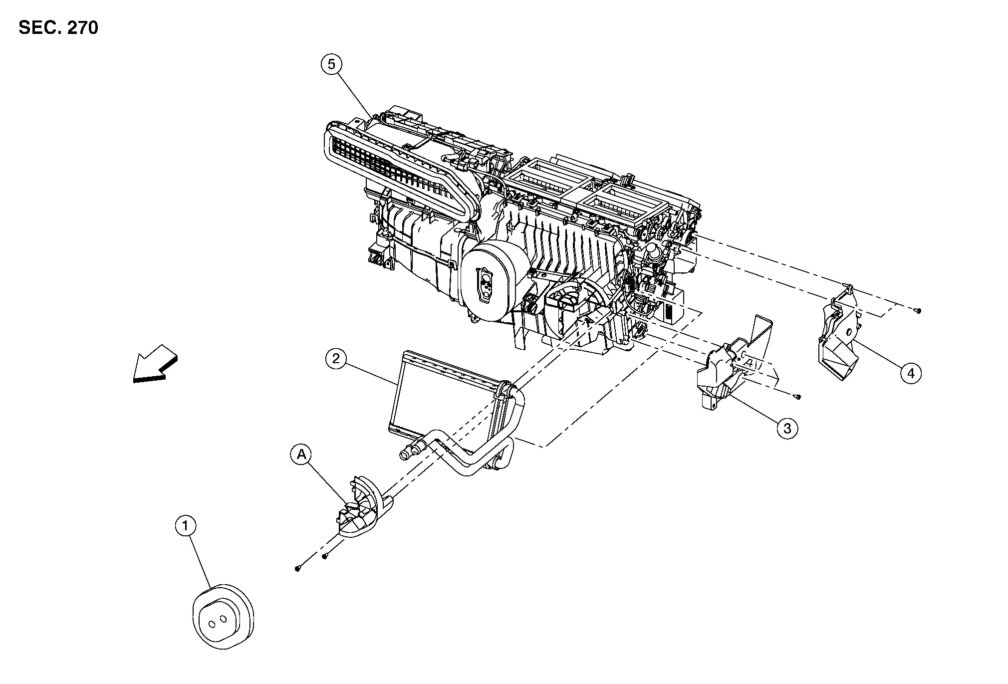
| 1. | Front heater core pipes grommet | 2. | Front heater core | 3. | Front heater core pipes cover |
| 4. | Front foot alignment duct (LH) | 5. | Front heating and cooling unit assembly | A. | Front heater core pipes support |
 |
Front |
Removal and Installation
REMOVAL
 NOTE:
NOTE:
When removing components such as hoses, lines/tubes, etc., cap or plug openings to prevent fluid from spilling.
Remove front heating and cooling unit assembly. Refer to Removal and Installation.
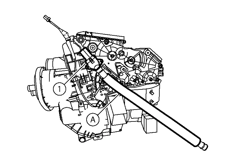
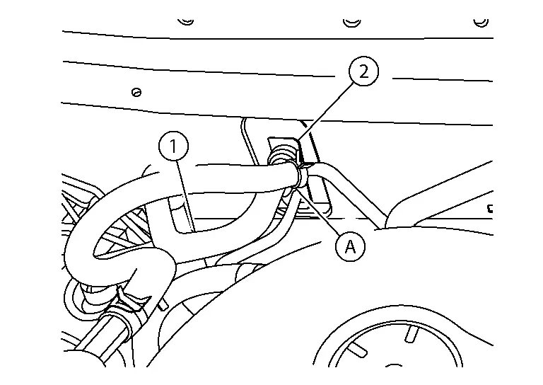
Disconnect aspirator tube (A) from aspirator duct (1) and remove aspirator duct.
Remove front foot duct (LH). Refer to Exploded View.
Remove front heater core pipes grommet.
Remove front heater core pipes support.
Remove front heater core pipes cover.
Remove front heater core.
CAUTION:
Cap or wrap the joint of the pipe with suitable material such as vinyl tape to avoid the entry of air.
INSTALLATION
Installation is in the reverse order of removal.
CAUTION:
-
Do not reuse O-rings.
-
Apply A/C oil to the O-rings of the rear evaporator for installation.
-
After charging the refrigerant, check for leaks. Refer to Leak Test.
Rear Heater Core Nissan Pathfinder Fifth generation
Exploded View
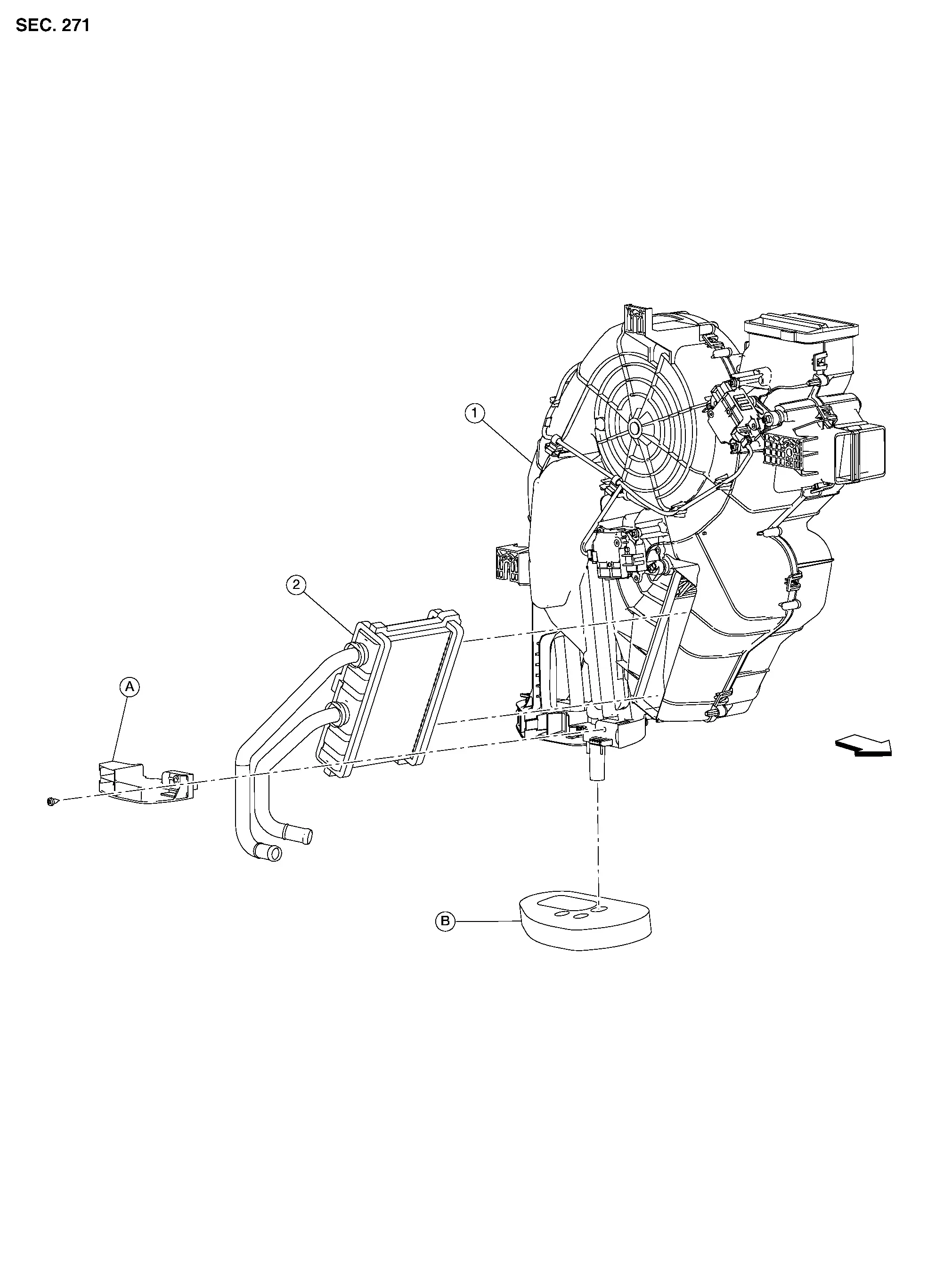
| 1. | Rear heater core | 2. | Rear heating and cooling unit assembly | A. | Rear heater core pipes grommet |
| B. | Rear heater core pipes support |
 |
Front |
Removal and Installation
REMOVAL
Remove rear heating and cooling unit assembly. Refer to Removal and Installation.
Remove screw retaining rear heater core pipes support to rear heating and cooling unit assembly. Refer to Exploded View.
Remove heater core pipes support.
Remove rear heater core pipes grommet.
Remove rear heater core.
CAUTION:
Cap or wrap the joint of the pipe with suitable material such as vinyl tape to avoid the entry of air.
INSTALLATION
Installation is in the reverse order of removal.
CAUTION:
-
Do not reuse O-rings.
-
Apply A/C oil to the O-rings of the rear evaporator for installation.
-
After charging the refrigerant, check for leaks. Refer to Leak Test.
Front Evaporator Nissan Pathfinder SUV
Exploded View
Front Heating and Cooling Unit Assembly Components
| 1. | Front heating and cooling unit assembly | 2. | Front heater core pipes cover | 3. | Foot duct (LH) |
| 4. | Front heater core | 5. | Foot duct (RH) | 6. | Mode door motor (front) |
| 7. | Air mix door motor (RH) | 8. | Expansion valve grommet | 9. | Intake sensor |
| 10. | Air mix door motor (LH) | 11. | Aspirator hose | 12. | Drain hose |
| 13. | Front blower unit assembly | 14. | In-cabin microfilter cover | 15. | Front blower motor |
| 16. | Intake door motor | 17. | Front blower unit | 18. | In-cabin microfilter |
| 19. | Blower motor intake packing | 20. | Front evaporator assembly | 21. | Front evaporator |
| 22. | O-rings | 23. | Front expansion valve | 24. | Front evaporator bolts |
Removal and Installation
REMOVAL
Remove front heating and cooling unit assembly. Refer to Removal and Installation.
Separate front blower unit case from front heating and cooling unit assembly.
Remove front heater core. Refer to Removal and Installation.
Remove front evaporator grommet.
Remove front heater case side cover.
Remove front evaporator cover screws.
Separate front heater case (lower) from front heater case (upper).
Disconnect harness connector from intake sensor, then remove intake sensor.
Separate front evaporator cover (lower) from front evaporator cover (upper).
Remove front evaporator.
CAUTION:
Cap or wrap the joint of the pipe with suitable material such as vinyl tape to avoid the entry of air.
Remove front expansion valve from front evaporator (if necessary). Refer to Removal and Installation.
INSTALLATION
Installation is in the reverse order of removal.
CAUTION:
-
Do not reuse O-rings.
-
Apply A/C oil to new O-rings for installation.
-
After charging the refrigerant, check for leaks. Refer to Leak Test.
-
A damaged or leaking air conditioning evaporator shall never be repaired or replaced with one removed from a used or salvaged Nissan Pathfinder vehicle. To replace a damaged or leaking evaporator, use only new and SAE J2842 certified evaporator(s).
Rear Evaporator Nissan Pathfinder 2026
Exploded View
| 1. | Intake sensor | 2. | Rear evaporator | 3. | O-ring |
| 4. | Rear expansion valve | 5. | Rear blower motor resistor | 6. | Rear blower motor |
| 7. | Rear heater core | 8. | Mode door motor (rear) | 9. | Air mix door motor (rear) |
| A. | Rear heating and cooling unit upper housing | B. | Rear heating and cooling unit lower housing |
 |
Front |
Removal and Installation
REMOVAL
Remove rear heater core. Refer to Removal and Installation.
Separate rear heating and cooling unit upper and lower housing to access rear evaporator. Refer to Exploded View.
Disconnect harness connector, then remove rear evaporator.
CAUTION:
Cap or wrap the joint of the pipe with suitable material such as vinyl tape to avoid the entry of air.
Remove rear expansion valve from rear evaporator (if necessary). Refer to Removal and Installation.
INSTALLATION
Installation is in the reverse order of removal.
CAUTION:
-
Do not reuse O-rings.
-
Apply A/C oil to the O-rings of the rear evaporator for installation.
-
After charging the refrigerant, check for leaks. Refer to Leak Test.
-
A damaged or leaking air conditioning evaporator shall never be repaired or replaced with one removed from a used or salvaged Nissan Pathfinder vehicle. To replace a damaged or leaking evaporator, use only new and SAE J2842 certified evaporator(s).
Front Expansion Valve Nissan Pathfinder Fifth generation
Exploded View
Front Heating and Cooling Unit Assembly Components

| 1. | Front heating and cooling unit assembly | 2. | Front heater core pipes cover | 3. | Foot duct (LH) |
| 4. | Front heater core | 5. | Foot duct (RH) | 6. | Mode door motor (front) |
| 7. | Air mix door motor (RH) | 8. | Expansion valve grommet | 9. | Intake sensor |
| 10. | Air mix door motor (LH) | 11. | Aspirator hose | 12. | Drain hose |
| 13. | Front blower unit assembly | 14. | In-cabin microfilter cover | 15. | Front blower motor |
| 16. | Intake door motor | 17. | Front blower unit | 18. | In-cabin microfilter |
| 19. | Blower motor intake packing | 20. | Front evaporator assembly | 21. | Front evaporator |
| 22. | O-rings | 23. | Front expansion valve | 24. | Front evaporator bolts |
Removal and Installation
REMOVAL
Discharge refrigerant. Refer to Recycle Refrigerant.
Remove cowl top cover. Refer to Removal and Installation.
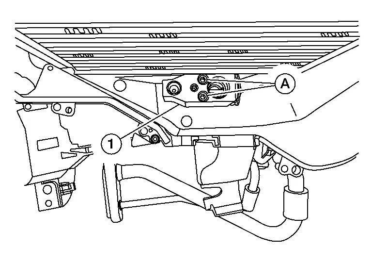
Remove nut (A), then disconnect high-pressure and low-pressure pipe (1) from expansion valve (2).
CAUTION:
Cap or wrap the joint of the pipe with suitable material such as vinyl tape to avoid the entry of air.
Remove front expansion valve bolts, then remove front expansion valve.
CAUTION:
Cap or wrap the joint of the pipe with suitable material such as vinyl tape to avoid the entry of air.
INSTALLATION
Installation is in the reverse order of removal.
CAUTION:
-
Do not reuse O-rings.
-
Apply A/C oil to the O-rings of the front expansion valve for installation.
-
After charging refrigerant, check for leaks. Refer to Leak Test.
Rear Expansion Valve Nissan Pathfinder SUV
Exploded View

| 1. | Intake sensor | 2. | Rear evaporator | 3. | O-ring |
| 4. | Rear expansion valve | 5. | Rear blower motor resistor | 6. | Rear blower motor |
| 7. | Rear heater core | 8. | Mode door motor (rear) | 9. | Air mix door motor (rear) |
| A. | Rear heating and cooling unit upper housing | B. | Rear heating and cooling unit lower housing |
 |
Front |
Removal and Installation
REMOVAL
Remove rear evaporator. Refer to Removal and Installation.
Remove bolt (A), then disconnect rear expansion valve pipe assembly (B) from rear expansion valve (1).
Remove bolts (A), then remove rear expansion valve (1).
CAUTION:
Cap or wrap the joint of the pipe with suitable material such as vinyl tape to avoid the entry of air.
INSTALLATION
Installation is in the reverse order of removal.
CAUTION:
-
Do not reuse O-rings.
-
Apply A/C oil to the O-rings of the rear expansion valve for installation.
-
After charging refrigerant, check for leaks. Refer to Leak Test.

Nissan Pathfinder (R53) 2022-2026 Service Manual
Heating and Cooling Unit Assembly
- Front Heating and Cooling Unit Assembly
- Rear Heating and Cooling Unit Assembly
- Front Heater Core
- Rear Heater Core
- Front Evaporator
- Rear Evaporator
- Front Expansion Valve
- Rear Expansion Valve
Contact Us
Nissan Pathfinder Info Center
Email: info@nipathfinder.com
Phone: +1 (800) 123-4567
Address: 123 Pathfinder Blvd, Nashville, TN 37214, USA
Working Hours: Mon–Fri, 9:00 AM – 5:00 PM (EST)
