Nissan Pathfinder: Heater & Air Conditioning System - Compressor
Compressor Nissan Pathfinder 2022
Exploded View
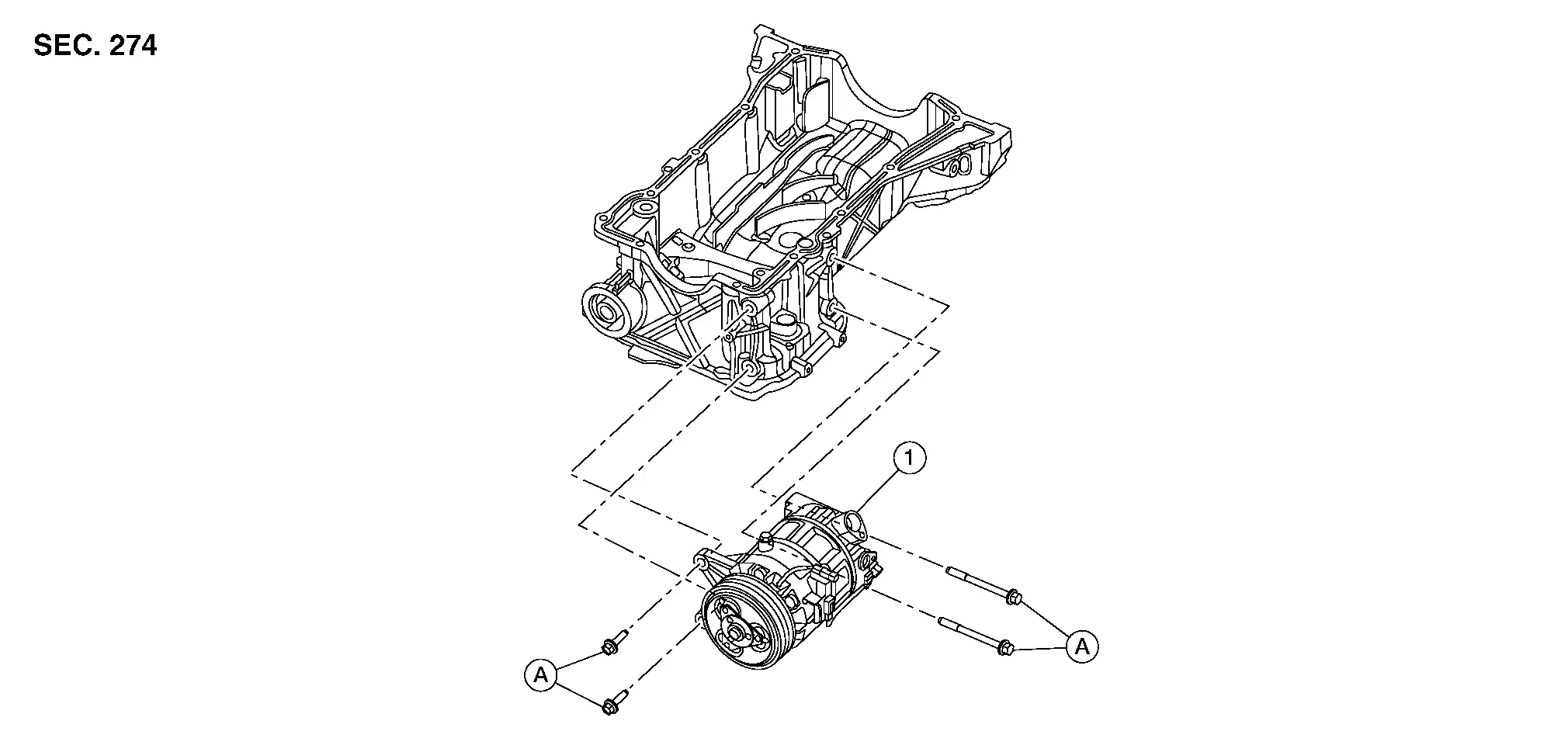
| 1. | Compressor | A. | Refer to Removal and Installation. |
Removal and Installation
REMOVAL
Discharge refrigerant. Refer to Recycle Refrigerant.
Remove front wheel and tire (RH). Refer to Removal and Installation.
Remove front under cover. Refer to Removal and Installation.
Remove bolts retaining water pipe to engine block, and set water pipe aside. Refer to Exploded View.
Remove drive belt. Refer to Removal and Installation.
Disconnect harness connectors from compressor.
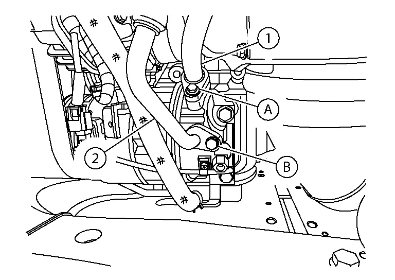
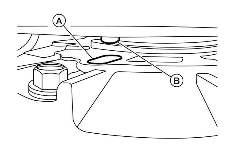
Remove bolt (A), then disconnect low-pressure flexible hose (1) from compressor.
CAUTION:
-
Cap or wrap the joint of the pipe with suitable material such as vinyl tape to avoid the entry of air.
-
Do not reuse O-ring.
| (2) | : High-pressure flexible hose |
| (B) | : Bolt |
Remove bolt (B), then disconnect high-pressure flexible hose (2) from compressor.

CAUTION:
-
Cap or wrap the joint of the pipe with suitable material such as vinyl tape to avoid the entry of air.
-
Do not reuse O-ring.
| (1) | : Low-pressure flexible hose |
| (A) | : Bolt |
Remove compressor bolts, then remove compressor.
INSTALLATION
Installation is in the reverse order of removal.
CAUTION:
Do not reuse O-rings.
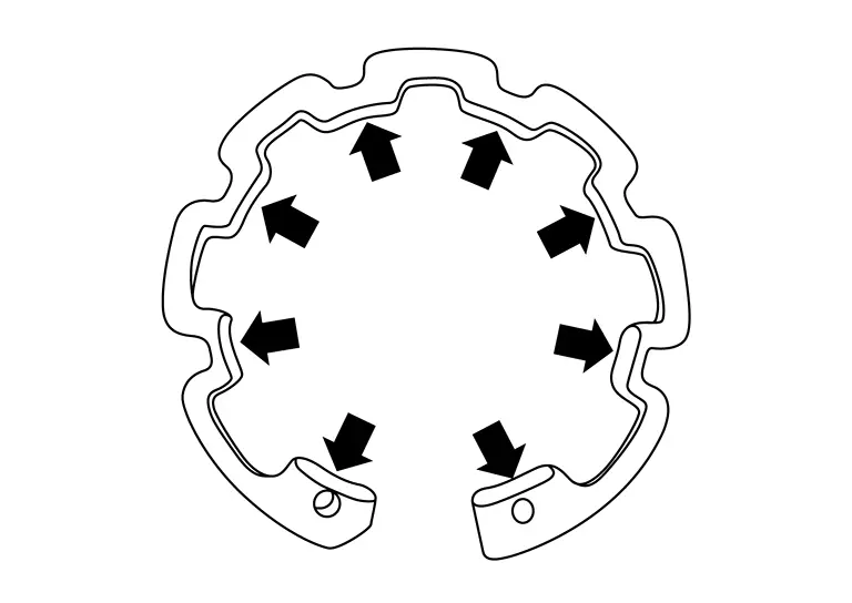
Finger tighten bolts in the sequence shown.
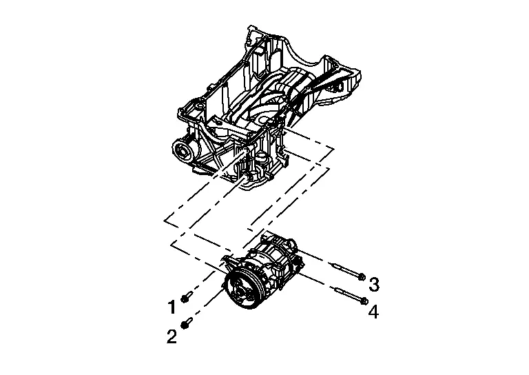
Tighten bolts to specified torque in the sequence shown.
| Bolts (1,2) | : 55.0 N·m (5.6 kg-m, 41.0 fl-lb) |
| Bolts (3,4) | : 61.3 N·m (6.3 kg-m, 45.0 fl-lb) |
Recharge refrigerant. Refer to Charge Refrigerant.
CAUTION:
After charging refrigerant, check for leaks. Refer to Leak Test.
Magnetic Clutch Nissan Pathfinder
Exploded View
Magnet Clutch Assembly
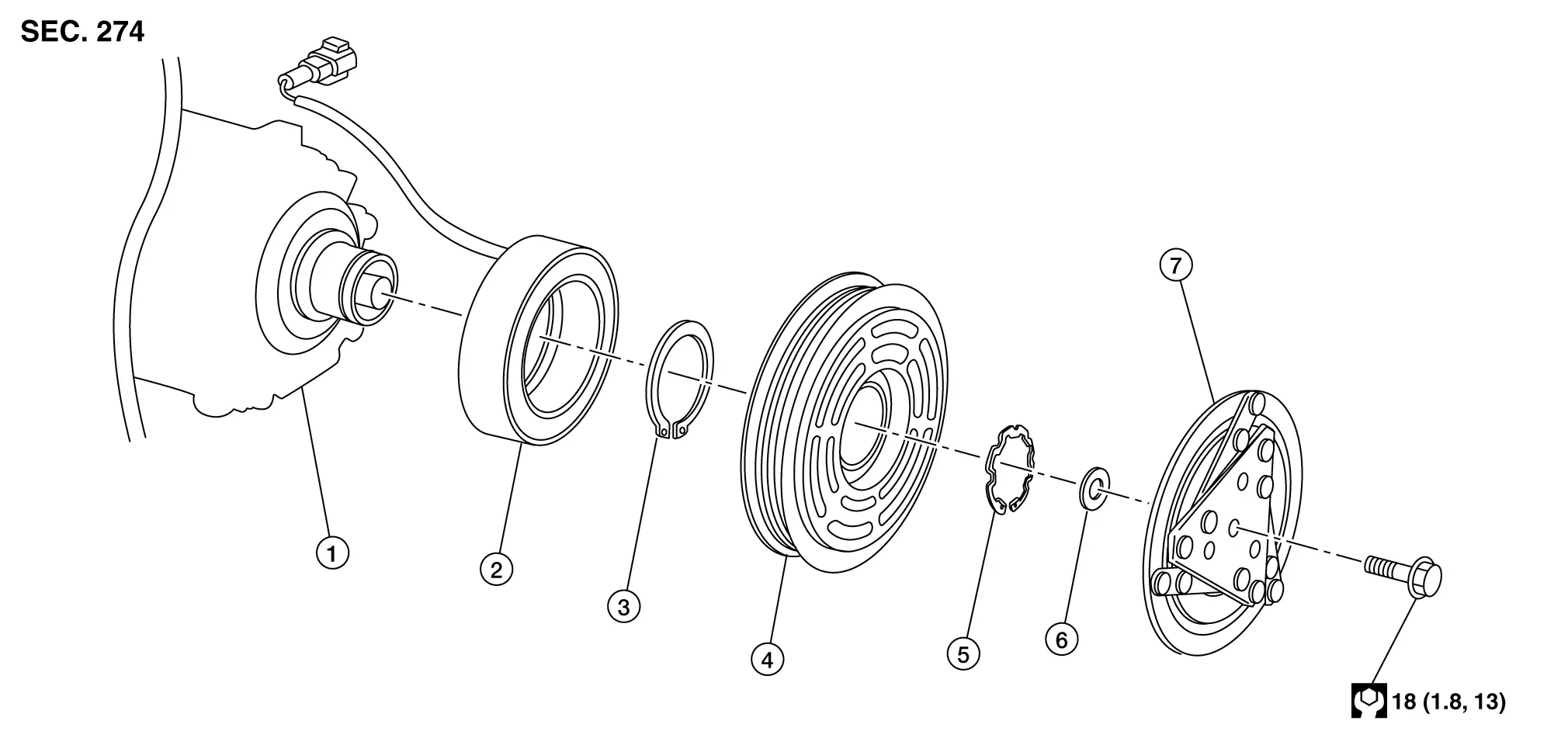
| 1. | Compressor | 2. | Magnet coil | 3. | Snap ring |
| 4. | Pulley | 5. | Snap ring | 6. | Shim(s) |
| 7. | Clutch disc |
Removal and Installation of Compressor Clutch
REMOVAL
Remove front wheel and tire (RH) using a power tool.
Remove front fender protector side cover (RH). Refer to Exploded View.
Remove front side of front fender protector (RH). Refer to Exploded View.
CAUTION:
Retain shim(s) for installation.
Remove drive belt. Refer to Removal and Installation.
Hold clutch disc using Tool (A) then remove bolt (B).
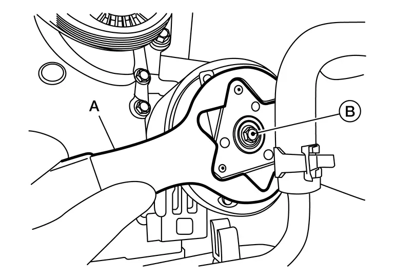
| Tool number (A) | : — (NI-52173) |
Remove clutch disk and shim(s).
CAUTION:
Retain shim(s) for installation.
Using a suitable tool (A) remove snap ring (B).
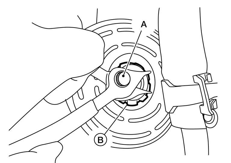
Remove pulley.
Disconnect harness connector from compressor.
Using a suitable tool release clip for harness connector (A).
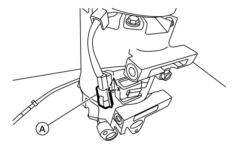
 |
: Clip |
Remove snap ring (A) using a suitable tool, then remove coil (1).
INSTALLATION
Installation is in reverse order of removal.
-
Make sure coil locating pin (B) is in slot (A).
CAUTION:
Make sure chamfered inner edge of pulley snap ring faces out-board.
INSPECTION AFTER INSTALLATION
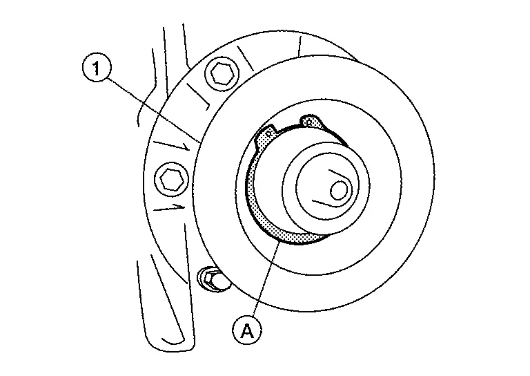
Check clearance (A) all around between clutch disc (1) and pulley (2) using a suitable tool.
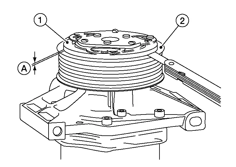
| Clutch disc-to-pulley clearance (B) | : Compressor |
CAUTION:
-
Replace magnetic clutch if specified clearance is not obtained.
-
Make sure magnet clutch assembly rotates smoothly before installing compressor.
BREAK-IN OPERATION
When replacing compressor clutch, always conduct the break-in operation. This is done by engaging and disengaging the clutch about 30 times. Break-in operation raises the level of transmitted torque.

Nissan Pathfinder (R53) 2022-2026 Service Manual
Compressor
Contact Us
Nissan Pathfinder Info Center
Email: info@nipathfinder.com
Phone: +1 (800) 123-4567
Address: 123 Pathfinder Blvd, Nashville, TN 37214, USA
Working Hours: Mon–Fri, 9:00 AM – 5:00 PM (EST)
