Nissan Pathfinder: Parking Brake System - Precautions. Preparation
Precautions Nissan Pathfinder SUV
Precaution for Supplemental Restraint System (SRS) "AIR BAG" and "SEAT BELT PRE-TENSIONER"
The Supplemental Restraint System such as “AIR BAG” and “SEAT BELT PRE-TENSIONER”, used along with a front seat belt, helps to reduce the risk or severity of injury to the driver and front passenger for certain types of collisions.
Information necessary to service the system safely is included in the “SRS AIR BAG” and “SEAT BELT” sections of this Service Manual.
WARNING:
Always observe the following items for preventing accidental activation:
-
To avoid rendering the SRS inoperative, which could increase the risk of personal injury or death in the event of a collision that would result in air bag inflation, it is recommended that all maintenance and repair be performed by an authorized NISSAN/INFINITI dealer.
-
Improper repair, including incorrect removal and installation of the SRS, can lead to personal injury caused by unintentional activation of the system. For removal of Spiral Cable and Air Bag Module, see “SRS AIR BAG”.
-
Never use electrical test equipment on any circuit related to the SRS unless instructed to in this Service Manual. SRS wiring harnesses can be identified by yellow and/or orange harnesses or harness connectors.
PRECAUTIONS WHEN USING POWER TOOLS (AIR OR ELECTRIC) AND HAMMERS
WARNING:
Always observe the following items for preventing accidental activation:
-
When working near the Air Bag Diagnosis Sensor Unit or other Air Bag System sensors with the ignition/power switch ON or engine running, never use air or electric power tools or strike near the sensor(s) with a hammer. Heavy vibration could activate the sensor(s) and deploy the air bag(s), possibly causing serious injury.
-
When using air or electric power tools or hammers, always switch the ignition/power switch OFF, disconnect the 12V battery or batteries, and wait at least 3 minutes before performing any service.
Precautions for Harness Repair
-
Solder the repaired area and wrap tape around the soldered area.
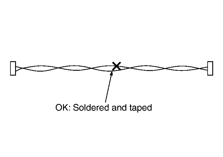
 NOTE:
NOTE:
A fray of twisted lines must be within 110 mm (4.33 in).
-
Bypass connection is never allowed at the repaired area.
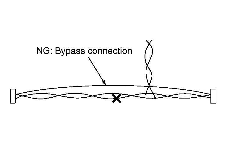
 NOTE:
NOTE:
Bypass connection may cause CAN communication error. The spliced wire becomes separated and the characteristics of twisted line are lost.
-
Replace the applicable harness as an assembly if error is detected on the shield lines of CAN communication line.
Precaution for Parking Brake System
WARNING:
Since dust covering the rear brakes has an effect on the human body, the dust must be removed using a dust collector. Do not splatter the dust with an air blow gun.
CAUTION:
-
When the parking brake must be released while the battery negative terminal is disconnected, or when a malfunction occurs in the electric parking brake system, the parking brake can be mechanically released. Perform the "INSTRUCTIONS FOR RELEASING PARKING BRAKE WHERE PARKING BRAKE SWITCH CANNOT BE USED". Refer to Description.
-
If mechanically releasing the parking brake or replacing the parking brake actuator, replace the rear brake caliper assembly and perform the "REMOVAL/REPLACEMENT OF REAR BRAKE PAD OR REAR BRAKE CALIPER". Refer to Description.
-
If replacing the ABS actuator and electric unit (control unit), perform the "ADDITIONAL SERVICE WHEN REPLACING ABS ACTUATOR AND ELECTRIC UNIT (CONTROL UNIT)". Refer to Work Procedure.
-
If replacing the chassis control module, perform the "ADDITIONAL SERVICE WHEN REPLACING CHASSIS CONTROL MODULE." Refer to Description.
-
When the parking brake is operated, the electric parking brake indicator lamp in the combination meter and the parking brake switch indicator turn ON.
-
When a malfunction occurs in the electric parking brake system, the electric parking brake warning lamp turns ON, the parking brake indicator lamp turns ON/OFF (depends on the parking brake system) or blinks, and the parking brake switch indicator turns ON/OFF (depends on the parking brake system) or blinks, and the function for entering the fail-safe status is held.
Precautions for Work
-
When removing or disassembling each component, be careful not to damage or deform it. If a component may be subject to interference, be sure to protect it with a shop cloth.
-
When removing (disengaging) components with a screwdriver or similar tool, be sure to wrap the component with a shop cloth or vinyl tape to protect it.
-
Protect the removed parts with a shop cloth and prevent them from being dropped.
-
Replace a deformed or damaged clip.
-
If a part is specified as a non-reusable part, always replace it with a new one.
-
Be sure to tighten bolts and nuts securely to the specified torque.
-
After installation is complete, be sure to check that each part works properly.
-
Follow the steps below to clean components:
-
Water soluble dirt:
-
Dip a soft cloth into lukewarm water, wring the water out of the cloth and wipe the dirty area.
-
Then rub with a soft, dry cloth.
-
-
Oily dirt:
-
Dip a soft cloth into lukewarm water with mild detergent (concentration: within 2 to 3%) and wipe the dirty area.
-
Then dip a cloth into fresh water, wring the water out of the cloth and wipe the detergent off.
-
Then rub with a soft, dry cloth.
-
-
Do not use organic solvent such as thinner, benzene, alcohol or gasoline.
-
For genuine leather seats, use a genuine leather seat cleaner.
-
Preparation Nissan Pathfinder Fifth generation
Special Service Tools
|
Tool number (TechMate No.) Tool name | Description | |
|---|---|---|
|
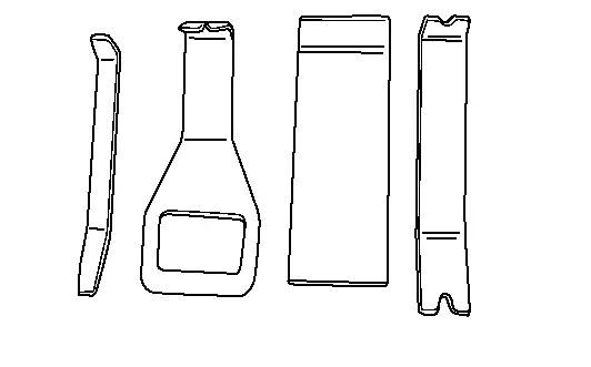
— (NI-46534) Trim Tool Set |
|
Removing trim components |
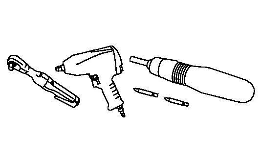
Commercial Service Tools
| Tool name | Description | |
| Power tool |
|
Loosening nuts, screws and bolts |

Nissan Pathfinder (R53) 2022-2026 Service Manual
Precautions. Preparation
Contact Us
Nissan Pathfinder Info Center
Email: info@nipathfinder.com
Phone: +1 (800) 123-4567
Address: 123 Pathfinder Blvd, Nashville, TN 37214, USA
Working Hours: Mon–Fri, 9:00 AM – 5:00 PM (EST)
