Nissan Pathfinder: Power Control System - System Description
- Component Parts
- System
- Diagnosis System (bcm)
- Diagnosis System (ipdm E/r)
- Diagnosis System (intelligent Key Unit)
Component Parts Nissan Pathfinder Fifth generation
Power Distribution System
Component Parts Location
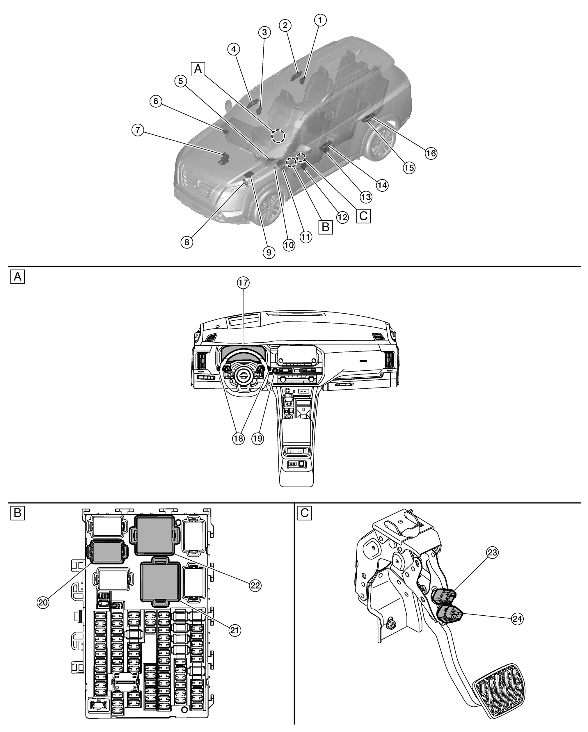
| A. | Instrument panel assembly | B. | Fuse block (J/B) [view with fuse block (J/B) removed] | C. | Brake pedal assembly (view with brake pedal assembly removed) |
| No. | Component | Function |
|---|---|---|
| 1. | Rear door lock assembly RH (door switch) |
Transmits the door switch signal to the BCM. Refer to Door Lock Assembly for detailed component location. |
| 2. | Rear door request switch RH (if equipped) |
Transmits the door request switch signal to the Intelligent Key unit. Refer to Door Request Switch for detailed component location. |
| 3. | Front door lock assembly RH (door switch) |
Transmits the door switch signal to the BCM. Refer to Door Lock Assembly for detailed component location. |
| 4. | Front door request switch RH |
Transmits the door request switch signal to the Intelligent Key unit. Refer to Door Request Switch for detailed component location. |
| 5. | Electric shift control module |
Transmits the shift position signal to the BCM via CAN communication. Refer to Electric Shift Control Module for detailed component location. |
| 6. | Intelligent Key unit |
The Intelligent Key Unit receives the push-button ignition switch input and transmits the signal to the BCM and IPDM E/R via CAN communication. Refer to Intelligent Key Unit for detailed component location. |
| 7. | ABS (Anti-lock Braking System) actuator and electric unit (control unit) |
Transmits the Nissan Pathfinder vehicle speed signal to the BCM via CAN communication. Refer to ABS Actuator and Electric Unit (Control Unit) for detailed component location. |
| 8. |
TCM (Transmission Control Module) |
The TCM transmits P (park) and N (neutral) signals to the BCM via CAN communication. Refer to TCM for detailed component location. |
| 9. |
IPDM E/R (Intelligent Power Distribution Module Engine Room) |
The IPDM E/R receives ignition relay (IPDM E/R) control signal and push-button ignition switch ON signal from the Intelligent Key unit via CAN communication, and controls the ignition relay (built into IPDM E/R). Refer to System Description. |
| 10. | Ignition relay-3 |
|
| 11. |
BCM (Body Control Module) |
|
| 12. | Front power window motor LH |
Transmits the front power window open/close signal to the BCM via LIN communication. Refer to Front Power Window Motor LH for detailed component location. |
| 13. | Front door lock assembly LH (door switch) |
Transmits the door switch signal to the BCM. Refer to Door Lock Assembly for detailed component location. |
| 14. | Front door request switch LH |
Transmits the door request switch signal to the Intelligent Key unit. Refer to Door Request Switch for detailed component location. |
| 15. | Rear door lock assembly LH (door switch) |
Transmits the door switch signal to the BCM. Refer to Door Lock Assembly for detailed component location. |
| 16. | Rear door request switch LH (if equipped) |
Transmits the door request switch signal to the Intelligent Key unit. Refer to Door Request Switch for detailed component location. |
| 17. | Combination meter |
Receives the ignition battery saver meter display signal from the BCM via CAN communication. Refer to Combination Meter (full TFT meter) or Combination Meter (7 inch information display) for detailed component location. |
| 18. | Combination switch |
Transmits the combination switch signal to the BCM. Refer to System Description. |
| 19. | Push-button ignition switch | Refer to Push-Button Ignition Switch. |
| 20. |
Ignition relay-1 [in fuse block (J/B)] |
|
| 21. |
Accessory relay [in fuse block (J/B)] |
|
| 22. |
Ignition relay-2 [in fuse block (J/B)] |
|
| 23. | Brake pedal position switch |
The brake pedal position switch detects that the brake pedal is depressed and transmits the signal to the BCM. Refer to Brake Pedal Position Switch for detailed component location. |
| 24. | Stop lamp switch |
The stop lamp switch detects that the brake pedal is depressed and transmits the signal to the BCM. Refer to Stop Lamp Switch for detailed component location. |
Push-Button Ignition Switch
-
The push-button ignition switch is installed in the center of the instrument panel.
-
When the push-button ignition switch is pressed it transmits the status signal to the Intelligent Key unit.
System Nissan Pathfinder Fifth generation
Power Distribution System
System Description
SYSTEM DIAGRAM
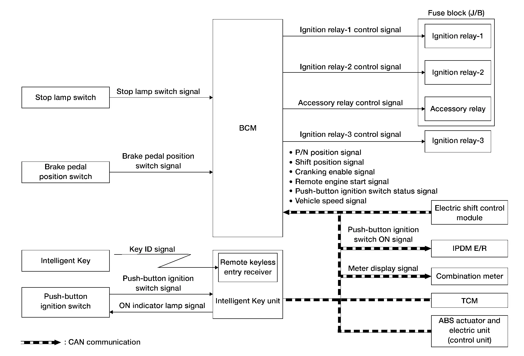
| Component | Function |
|---|---|
| Intelligent Key | Operates based on the results of electronic ID verification using two-way communication between the Intelligent Key and the Nissan Pathfinder vehicle (Intelligent Key unit). |
| Push-button ignition switch | Refer to Push-Button Ignition Switch. |
| Stop lamp switch | Stop lamp switch detects that brake pedal is depressed, and then transmits ON/OFF signal to BCM. |
| Brake pedal position switch | Brake pedal position switch detects that brake pedal is depressed, and then transmits ON/OFF signal to BCM. |
| TCM | Transmits shift position signal and cranking enable signal to BCM via CAN communication. |
| Electric shift control module | Transmits the P/N position signal to the BCM via CAN communication. |
| Intelligent Key unit | Transmits push-button ignition switch status signal and remote engine start signal to BCM via CAN communication. |
| ABS actuator and electric unit (control unit) | Transmits Nissan Pathfinder vehicle speed signal to BCM via CAN communication. |
| BCM |
|
| Combination meter | Combination meter turns the ignition battery saver operation notice/operation confirmation ON according to the request from BCM via CAN communication. |
| Ignition relay-1 [Fuse block (J/B)] | Controlled by BCM and turns ON/OFF the battery power supply to each parts. |
| Ignition relay-2 [Fuse block (J/B)] | |
| Ignition relay-3 | |
| Accessory relay [Fuse block (J/B)] | |
| IPDM E/R | IPDM E/R controls the integrated ignition relay, and supplies voltage to the load according to the request from BCM via CAN communication. |
Signal transmission function list
| Signal name | Input | Output | Description |
|---|---|---|---|
| Stop lamp switch signal | Stop lamp switch | BCM | Transmits the stop lamp switch signal to the BCM. |
| Brake pedal position switch signal | Brake pedal position switch | BCM | Transmits the brake pedal position switch signal to the BCM. |
| Push-button ignition switch signal | Push-button ignition switch | Intelligent Key unit | Transmits the push-button ignition switch signal to the Intelligent Key unit. |
| P/N position signal | Electric shift control module | BCM (CAN) | Transmits the P/N position signal via CAN communication. |
| Shift position signal | TCM | BCM (CAN) | Transmits the shift position signal via CAN communication. |
| Cranking enable signal | TCM | BCM (CAN) | Transmits the cranking enable signal via CAN communication. |
| Remote engine start signal | Intelligent Key unit | BCM (CAN) | Transmits the remote engine start signal via CAN communication. |
| Push-button ignition switch status signal | Intelligent Key unit | BCM (CAN) | Transmits the push-button ignition switch status signal via CAN communication. |
| Nissan Pathfinder Vehicle speed signal | ABS actuator and electric unit (control unit) | BCM (CAN) | Transmits the Nissan Pathfinder vehicle speed signal via CAN communication. |
| Push-button ignition switch ON signal | BCM | IPDM E/R (CAN) | Transmits the push-button ignition switch ON signal via CAN communication. |
| Meter display signal | BCM | Combination meter (CAN) | Transmits the meter display signal via CAN communication. |
SYSTEM DESCRIPTION
-
The POWER DISTRIBUTION SYSTEM (PDS) is the system that the BCM controls with the operation of the push-button ignition switch and performs the power distribution to each power circuit. This system is used instead of the mechanical power supply changing mechanism with the operation of the conventional key cylinder.
Allocation to the accessory power supply, refer to the auto ACC function. Refer to System Description.
-
The push-button ignition switch can be operated when the Intelligent Key is in the following conditions:
-
Intelligent Key is in the detection area of the inside key antenna.
-
Intelligent Key backside is contacted to push-button ignition switch.
-
-
Push-button ignition switch operation is an input to the Intelligent Key unit as a signal. The Intelligent Key unit transmits the push-button ignition switch status and remote engine start signal to the BCM via CAN communication. The BCM changes the push-button ignition switch mode according to the status and operates the following relays to supply power to each power circuit:
-
Ignition relay (IPDM E/R)
-
Ignition relay-1 [Fuse block(J/B)]
-
Ignition relay-2 [Fuse block(J/B)]
-
Ignition relay-3
-
Accessory relay -1 [Fuse block(J/B)]
-
IGNITION BATTERY SAVER SYSTEM
The ignition battery saver system is a system in which the BCM automatically shuts off the power supply (push-button ignition switch ON -> OFF) to protect the battery.
The BCM activates the ignition battery saver system 10 minutes after the ignition battery saver timer function operating conditions are met. Also, the meter display signal is transmitted to the combination meter via CAN communication as operation notice and operation confirmation, and the information display is operated.
Operating Condition of Ignition Battery Saver Timer Function
When all the following conditions are met for 10 minutes, the battery saver system will cut off the power supply (push-button ignition switch ON -> OFF) to prevent battery discharge:
-
Push-button ignition switch is ON
-
Engine stopped
Cancel Condition of Ignition Battery Saver Timer Function
If any of the following conditions are met the battery saver timer function is canceled:
 CONSULT
-
Push-button ignition switch is not ON.
-
Engine running
-
Select "Diagnosis (ALL system)" of "BCM"
 NOTE:
NOTE:
Ignition battery saver timer function will return 1 minute or more, after closing CONSULT or removing VI from the Nissan Pathfinder vehicle.
Operation Notice Function (7 Minutes have Passed Since the Timer was Activated)
7 minutes after ignition battery saver timer is activated, information display (message display) is activated as and operation notice.
|
Combination meter (Information display) | |
|---|---|
| Operation | "Power will turn off to save the battery" |
| Operating time | Approx. 3 minutes |
Operation Confirmation Function (10 Minutes have Passed Since the Timer was Activated)
10 minutes after ignition battery saver timer is activated, information display (message display) is activated as and operation confirmation.
|
Combination meter (Information display) | |
|---|---|
| Operation | "Power turned off to save the battery" |
| Operating time | Approx. 1 minutes |
Temporarily Disabling the Ignition Battery Saver System
The ignition battery saver system can be temporarily disabled, without using CONSULT, to prevent it from functioning when performing trouble diagnosis. Refer to Diagnosis Procedure.
POWER SUPPLY POSITION CHANGE TABLE BY PUSH-BUTTON IGNITION SWITCH OPERATION
The power supply position changing operation can be performed with the following operations:
 NOTE:
NOTE:
-
When an Intelligent Key is within the detection area of inside key antenna and when Intelligent Key backside is contacted to push-button ignition switch, it is equivalent to the operations below.
-
When starting the engine, the BCM monitors under the engine start conditions:
-
Brake pedal operating condition
-
Shift selector position
-
Nissan Pathfinder Vehicle speed
-
Vehicle speed: less than 2.5 MPH (4 km/h)
| Power supply position | Engine start/stop condition | Push-button ignition switch operation frequency | |
|---|---|---|---|
| Shift selector position | Brake pedal operation condition | ||
| OFF → ACC | — | Not depressed | 1 |
| OFF → ACC → ON | — | Not depressed | 2 |
| OFF → ACC → ON → OFF | — | Not depressed | 3 |
|
OFF → START ACC → START ON → START |
P or N position | Depressed | 1 |
| Engine is running → OFF | — | — | 1 |
Vehicle speed: 2.5 MPH (4 km/h) or more
| Power supply position | Engine start/stop condition | Push-button ignition switch operation frequency | |
|---|---|---|---|
| Shift selector position | Brake pedal operation condition | ||
| Engine is running → ACC | — | — | Emergency stop operation |
| Engine stall return operation while driving | N position | Not depressed | 1 |
Emergency stop operation
-
Press and hold the push-button ignition switch for 2 seconds or more.
-
Press the push-button ignition switch 3 times or more within 1.5 seconds.
Auto Acc Function
System Description
SYSTEM DIAGRAM
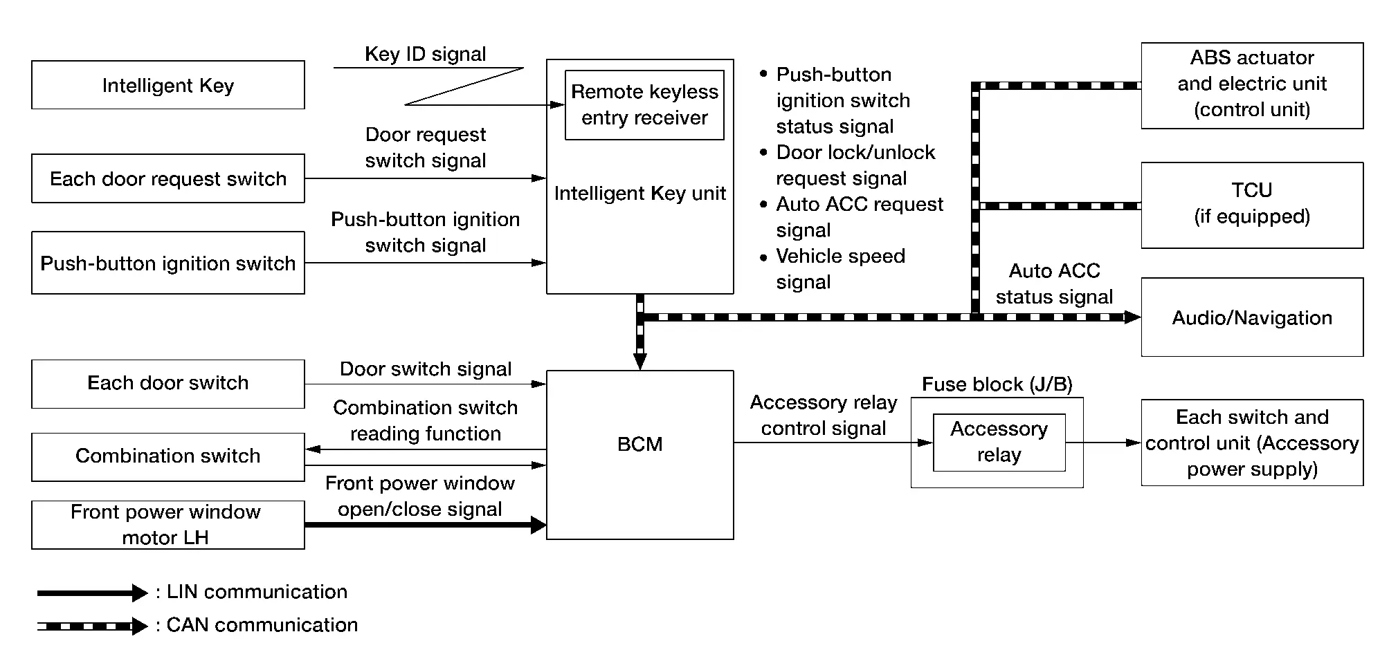
| Component | Function |
|---|---|
| Intelligent Key | Operates based on the results of electronic ID verification using two-way communication between the Intelligent Key and the Nissan Pathfinder vehicle (Intelligent Key unit). |
| Each door request switch | Detects door lock/unlock operation. |
| Push-button ignition switch | Refer to Push-Button Ignition Switch. |
| Each door switch | Detects door open/close condition. |
| Combination switch | Inputs the each switch condition signal to BCM. |
| Front power window motor LH | Transmits front power window open/close signal to BCM via LIN communication. |
| Intelligent Key unit | Transmits push-button ignition switch status signal and door lock/unlock request signal to BCM via CAN communication. |
| ABS actuator and electric unit (control unit) | Transmits Nissan Pathfinder vehicle speed signal to the BCM via CAN communication. |
| TCU | Transmits auto ACC request signal to BCM via CAN communication. |
| BCM | BCM operates the auto ACC function based on each signal state. |
| Accessory relay | Controlled by the BCM and turns ON/OFF the battery power supply to each parts. |
| Audio/Navigation |
|
Signal transmission function list
| Signal name | Input | Output | Description |
|---|---|---|---|
| Door request switch signal | Each door request switch | Intelligent Key unit | Transmits the door request switch signal to the Intelligent Key unit. |
| Push-button ignition switch signal | Push-button ignition switch | Intelligent Key unit | Transmits the push-button ignition switch signal to the Intelligent Key unit. |
| Door switch signal | Each door switch | BCM | Transmits the door switch signal to the BCM. |
| Combination switch signal | Combination switch | BCM | Transmits the combination switch signal to the BCM. |
| Front power window open/close signal | Front power window motor LH | BCM (LIN) | Transmits the front power window open/close signal via LIN communication. |
| Push-button ignition switch status signal | Intelligent Key unit | BCM (CAN) | Transmits the push-button ignition switch status signal via CAN communication. |
| Door lock/unlock request signal | Intelligent Key unit | BCM (CAN) | Transmits the door lock/unlock request signal via CAN communication. |
| Auto ACC request signal |
|
BCM (CAN) | Transmits the auto ACC request signal via CAN communication. |
| Auto ACC status signal | BCM | Audio/Navigation (CAN) | Transmits the auto ACC status signal via CAN communication. |
| Nissan Pathfinder Vehicle speed signal | ABS actuator and electric unit (control unit) | BCM (CAN) | Transmits the Nissan Pathfinder vehicle speed signal via CAN communication. |
SYSTEM DESCRIPTION
In conventional vehicles, power is supplied to the accessories of the vehicle after the push-button ignition switch is placed to ACC.
The AUTO ACC function is a function that bypasses the push-button ignition switch ACC mode and automatically distributes accessory power supply to each switch and unit based on door unlock operation, etc. using the Intelligent Key.
OPERATION FLOW
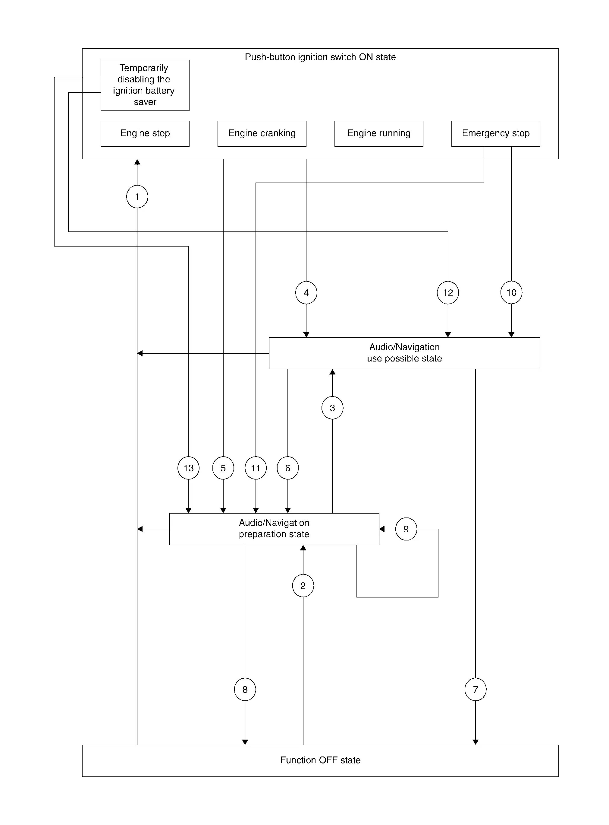
Push-button ignition switch ON state
In this status the push-button ignition switch is operated and placed ON.
Audio/Navigation use possible state
-
In this status the audio/navigation, and each switch and unit that is activated by the accessory power supply can be operated.
-
When 10 minutes pass after conditions are satisfied while audio/navigation are not operated, audio/navigation turns OFF.
Audio/Navigation preparation state
-
In this status audio/navigation are stopped, but the switches and units other than those for audio/navigation that can operate by using the accessory power supply are available until the accessory power supply turns OFF.
-
When audio/navigation is operated within 1 minutes after conditions are satisfied, operation time is extended for 10 minutes. Audio/navigation can be operated for a maximum of 30 minutes after the status is satisfied.
Function OFF state
In this status the AUTO ACC function stops and power to the accessories is not supplied.
| No. | Function status | Shifting condition | Accessory power supply |
|---|---|---|---|
 |
Shifting from “Function OFF state” to "Push-button ignition switch ON state" |
Any of the following conditions are satisfied:
|
OFF –> ON |
| Shifting from “Audio/Navigation preparation state” to “Push-button ignition switch ON state” | ON | ||
| Shifting from “Audio/Navigation use possible state” to “Push-button ignition switch ON state” | ON | ||
 |
Shifting from “Function OFF state” to “Audio/Navigation preparation state” |
Any of the following conditions are satisfied:
|
OFF –> ON |
 |
Shifting from “Audio/Navigation preparation state” to “Audio/Navigation use possible state” | Operate audio/navigation. | ON |
 |
Shifting from “Push-button ignition switch ON state” to “Audio/Navigation use possible state” | Push-button ignition switch OFF from ON while front door LH is closed with Nissan Pathfinder vehicle speed is less than 2 MPH (3 km/h). | ON |
 |
Shifting from “Push-button ignition switch ON state” to “Audio/Navigation preparation state” | Push-button ignition switch OFF from ON while front door LH is open with Nissan Pathfinder vehicle speed is less than 2 MPH (3 km/h). | ON |
 |
Shifting from “Audio/Navigation use possible state” to “Audio/Navigation preparation state” |
Any of the following conditions are satisfied:
|
ON |
 |
Shifting from “Audio/Navigation use possible state” to “Function OFF state” | 30 minutes pass from “Audio/Navigation use possible state”. | ON –> OFF |
 |
Shifting from “Audio/Navigation preparation state” to “Function OFF state” | 1 minutes or 3 minutes pass from “Audio/Navigation preparation state”. | ON –> OFF |
 |
Shifting from “Audio/Navigation use possible state” time extension (1 minute) |
Any of the following conditions are satisfied:
|
ON |
 |
Shifting from “Push-button ignition switch ON state” (in status of emergency stop) to “Audio/Navigation use possible state” | Nissan Pathfinder Vehicle speed is less than 2 MPH (3 km/h) and except front door LH is opened. | ON |
 |
Shifting from “Push-button ignition switch ON state” (in status of emergency stop) to “Audio/Navigation preparation state” | Nissan Pathfinder Vehicle speed is less than 2 MPH (3 km/h) and front door LH is opened. | ON |
 |
Shifting from “Push-button ignition switch ON state” (in status of temporarily disabling the ignition battery saver) to “Audio/Navigation use possible state” |
Press and hold the push-button ignition switch continuously for 3 seconds or more when all of the following conditions are satisfied:
|
ON |
 |
Shifting from “Push-button ignition switch ON state” (in status of temporarily disabling the ignition battery save) to “Audio/Navigation preparation state” |
Press and hold the push-button ignition switch continuously for 3 seconds or more when all of the following conditions are satisfied:
|
ON |
Diagnosis System (bcm) Nissan Pathfinder 5th Gen
Common Item
CONSULT Function (BCM - COMMON ITEM)
| BCM | Refer to CONSULT Function (BCM - COMMON ITEM). |
Intelligent Key
CONSULT Function (BCM - INTELLIGENT KEY)
| BCM | Refer to CONSULT Function (BCM - INTELLIGENT KEY). |
Diagnosis System (ipdm E/r) Nissan Pathfinder 5th Gen
CONSULT Function (IPDM E/R)
| IPDM E/R | Refer to CONSULT Function (IPDM E/R). |
Diagnosis System (intelligent Key Unit) Nissan Pathfinder
CONSULT Function (HANDS FREE MODULE)
| Intelligent Key unit | Refer to CONSULT Function (HANDS FREE MODULE). |

Nissan Pathfinder (R53) 2022-2026 Service Manual
System Description
- Component Parts
- System
- Diagnosis System (bcm)
- Diagnosis System (ipdm E/r)
- Diagnosis System (intelligent Key Unit)
Contact Us
Nissan Pathfinder Info Center
Email: info@nipathfinder.com
Phone: +1 (800) 123-4567
Address: 123 Pathfinder Blvd, Nashville, TN 37214, USA
Working Hours: Mon–Fri, 9:00 AM – 5:00 PM (EST)
