Nissan Pathfinder: Power Control System - System Description
Component Parts Nissan Pathfinder 5th Gen
Ipdm E/r
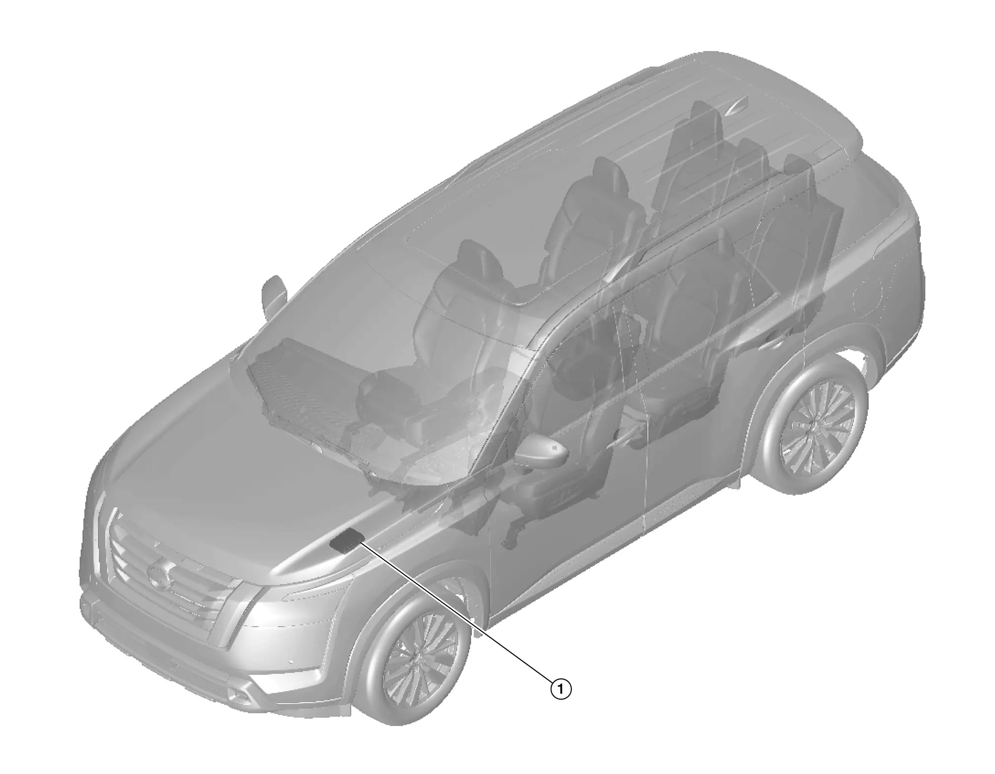
Component Parts Location
| No. | Component | Function |
|---|---|---|
| 1. |
IPDM E/R (Intelligent Power Distribution Module Engine Room) |
Refer to System Description. |
System Nissan Pathfinder 2022
Relay Control System
System Description
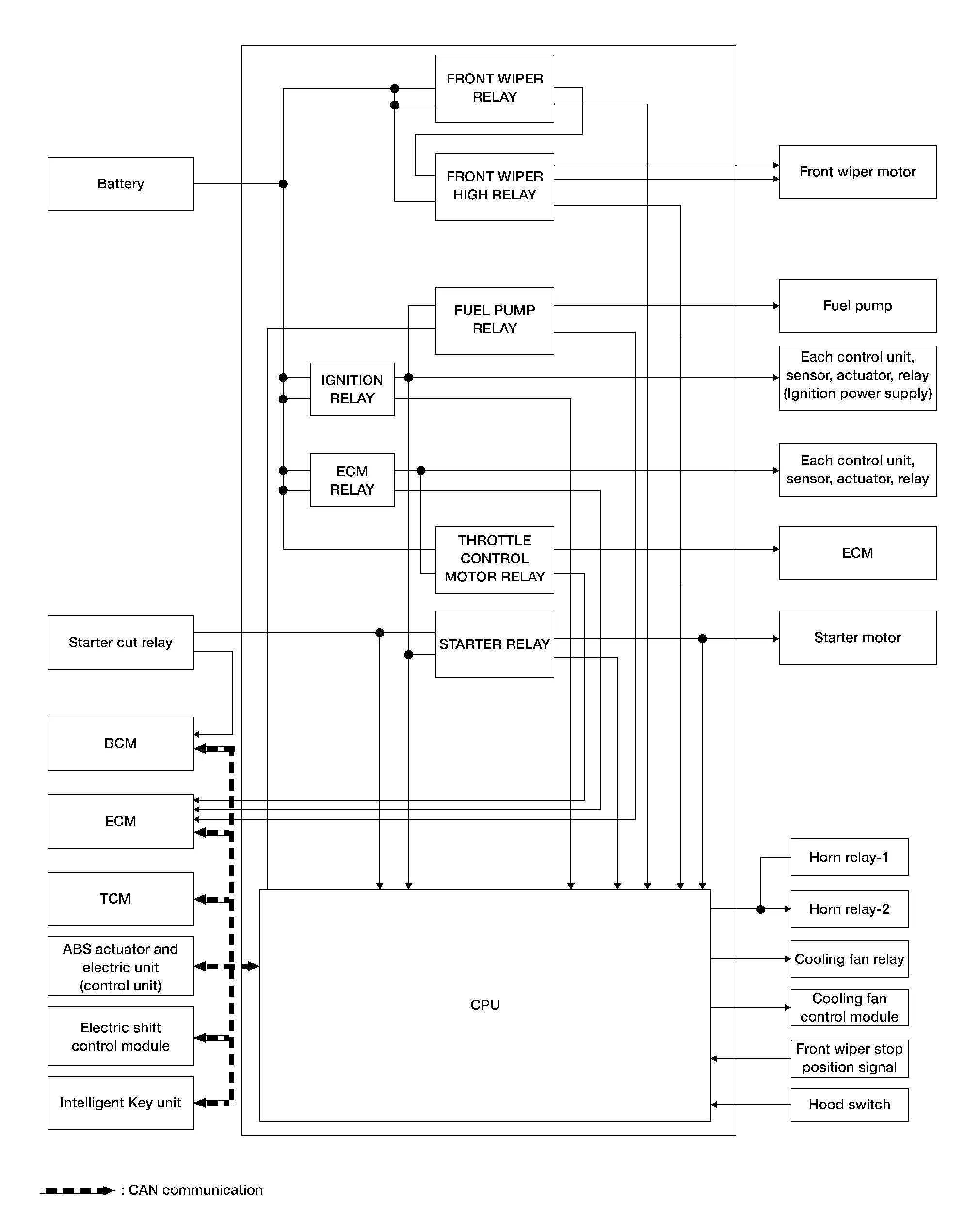
SYSTEM DIAGRAM
DESCRIPTION
The IPDM E/R activates the internal control circuit to perform relay ON-OFF control according to the input signals from various sensors and the request signals received from control units via CAN communication.
 NOTE:
NOTE:
IPDM E/R integrated relays cannot be removed.
| Control relay | Input/output | Transmit unit | Control part | Reference |
|---|---|---|---|---|
|
Front wiper request signal | BCM (CAN) | Front wiper motor | System Description (With Rain Sensing From Wipers) or System Description (Without Rain Sensing From Wipers) |
| Front wiper stop position signal | Front wiper motor | |||
| Starter relay | Ignition switch ON signal | BCM (CAN) | Starter motor | System Description (without stop/start system) or System Description (with stop/start system) |
| Cranking enable (ECM) signal | ECM (CAN) | |||
| Cranking enable (TCM) signal | TCM (CAN) | |||
| Ignition relay | Ignition switch ON signal | BCM (CAN) | Each control unit, sensor, actuator, relay (Ignition power supply) | — |
| Nissan Pathfinder Vehicle speed signal | ABS actuator and electric unit (control unit) (CAN) |
 NOTE:
NOTE:
ECM controls the following relays:
-
ECM relay
-
Fuel pump relay
-
Throttle control motor relay
Smart Field-Effect Transistor (fet)
System Description
SYSTEM DESCRIPTION
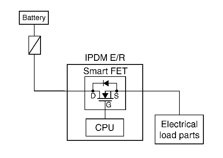
A Smart Field-Effect Transistor (FET) is a transistor used to monitor and control current flow on module outputs. The IPDM E/R uses a Smart FET protection strategy to prevent module damage in the event of excessive current flow. The Smart FET protection strategy monitors its outputs for excessive current, and when a fault occurs, shuts down the output and records a DTC.
COMPONENT FUNCTION WITHIN SYSTEM
-
The Smart FET turns the each lamps ON according to the request from the BCM.
-
The Smart FET turns the A/C compressor (magnetic clutch) ON according to the request from the ECM.
INDIVIDUAL COMPONENT FUNCTION
The Smart FET supplies power supply voltage to the each lamp and the A/C compressor (magnetic clutch).
COMPONENT OPERATION
The Smart FET, that uses MOS field effect transistor, is adopted for each lamp and the A/C compressor (magnetic clutch) control.
 NOTE:
NOTE:
A MOS field effect transistor is a transistor in which the gate is composed of a metal-oxide-semiconductor (MOS). Field effect transistor is controlled by voltage, while ordinary transistor is controlled by current. Electrode of field effect transistor is called source, drain, or gate, while electrode of ordinary transistor is called emitter, collector, or base.
Power Control System
System Description
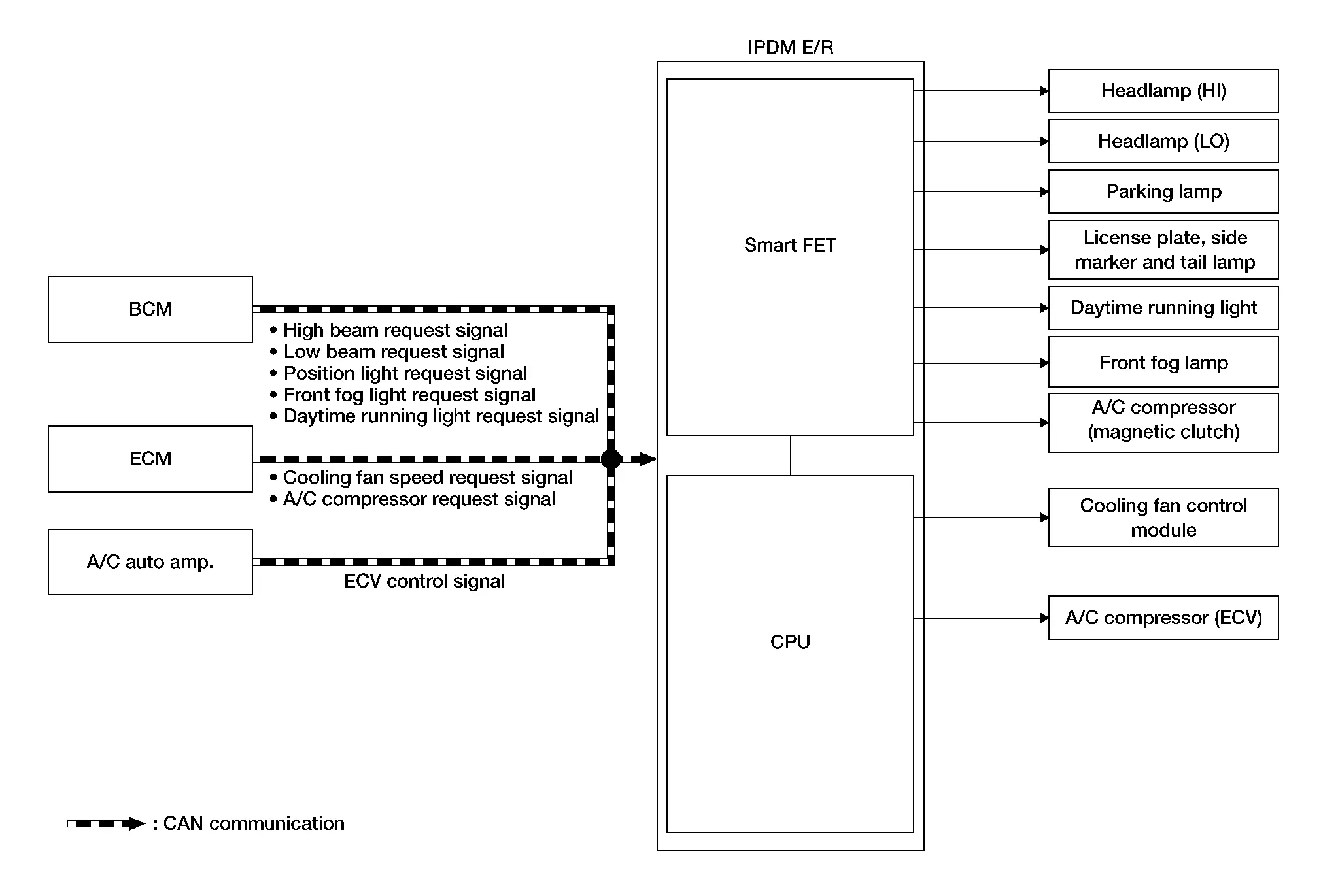
SYSTEM DIAGRAM
| Component | Function |
|---|---|
| Smart FET | Refer to Component Description. |
| Headlamp (HI) | The IPDM E/R supplies power supply voltage to each lamp, and turns the each lamp ON. |
| Headlamp (LO) | |
| Parking lamp | |
| License plate, side marker and tail lamp | |
| Daytime running light | |
| Front fog lamp | |
| A/C compressor (magnetic clutch) | The IPDM E/R supplies power supply voltage to the A/C compressor (magnetic clutch), and turns the magnet clutch ON. |
| Cooling fan module | The IPDM E/R controls each actuator. |
| A/C compressor (ECV) |
INPUT SIGNAL AND OUTPUT SIGNAL
Major signal transmission between each unit via communication lines is shown in the following table:
| Component parts | Signal description |
|---|---|
| BCM | The BCM transmits the ON/OFF request signal for each lamp to IPDM E/R via CAN communication. |
| ECM |
|
| A/C auto amp. | The A/C auto amp. transmits the ECV control signal to the IPDM E/R via CAN communication. |
| IPDM E/R |
|
Power Consumption Control System
System Description
SYSTEM DIAGRAM
INPUT SIGNAL AND OUTPUT SIGNAL
Major signal transmission between each unit via communication lines is shown in the following table:
| Component parts | Signal description |
|---|---|
| BCM |
|
| IPDM E/R |
|
| Combination meter | |
| Intelligent Key unit | |
| AV control unit | |
| TCU | |
| 8CH CAN gateway | |
| ABS actuator and electric unit (control unit) | |
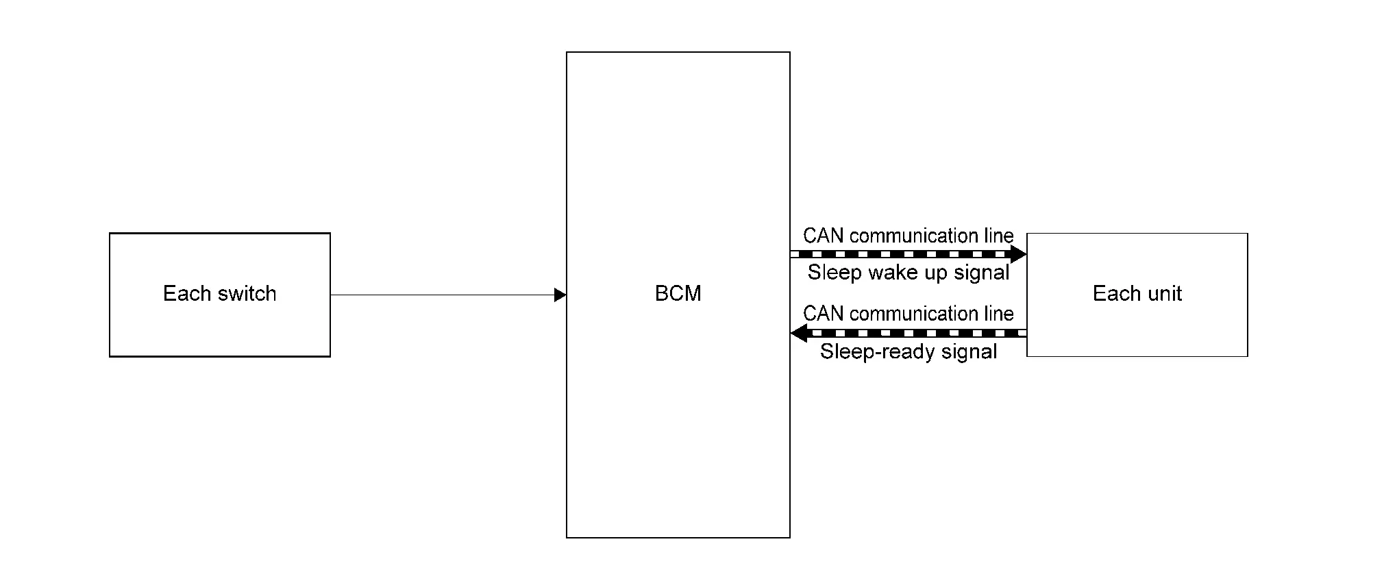
| Each switch | Each switch transmits the Nissan Pathfinder vehicle status to BCM. |
DESCRIPTION
Outline
-
IPDM E/R incorporates a power consumption control function that reduces the power consumption according to the Nissan Pathfinder vehicle status.
-
IPDM E/R changes its status (control mode) with the sleep wake up signal received from BCM via CAN communication.
Normal mode (wake-up)
-
CAN communication is normally performed with other control units.
-
Individual unit control by IPDM E/R is normally performed.
Low power consumption mode (sleep)
-
Low power consumption control is active.
-
CAN transmission is stopped.
-
Sleep Mode Activation
-
IPDM E/R judges that the sleep-ready conditions are fulfilled when the ignition switch is OFF and none of the conditions below are present. Then it transmits a sleep-ready signal (ready) to BCM via CAN communication.
-
Outputting signals to actuators
-
Output requests are being received from control units via CAN communication.
-
-
IPDM E/R stops CAN communication and enters the low power consumption mode when it receives a sleep wake up signal (sleep) from BCM and the sleep-ready conditions are fulfilled.
Wake-Up Operation
-
IPDM E/R changes from the low power consumption mode to the normal mode when it receives a sleep wake up signal (wake up) from the BCM or any of the following conditions are fulfilled. In addition, it transmits a sleep-ready signal (not-ready) to BCM via CAN communication to report the CAN communication start.
-
Ignition switch ON
-
Hood switch status changes.
-
An output request is received from a control unit via CAN communication.
-
Signal Buffer System
System Description
SYSTEM DIAGRAM
| Component | Function |
|---|---|
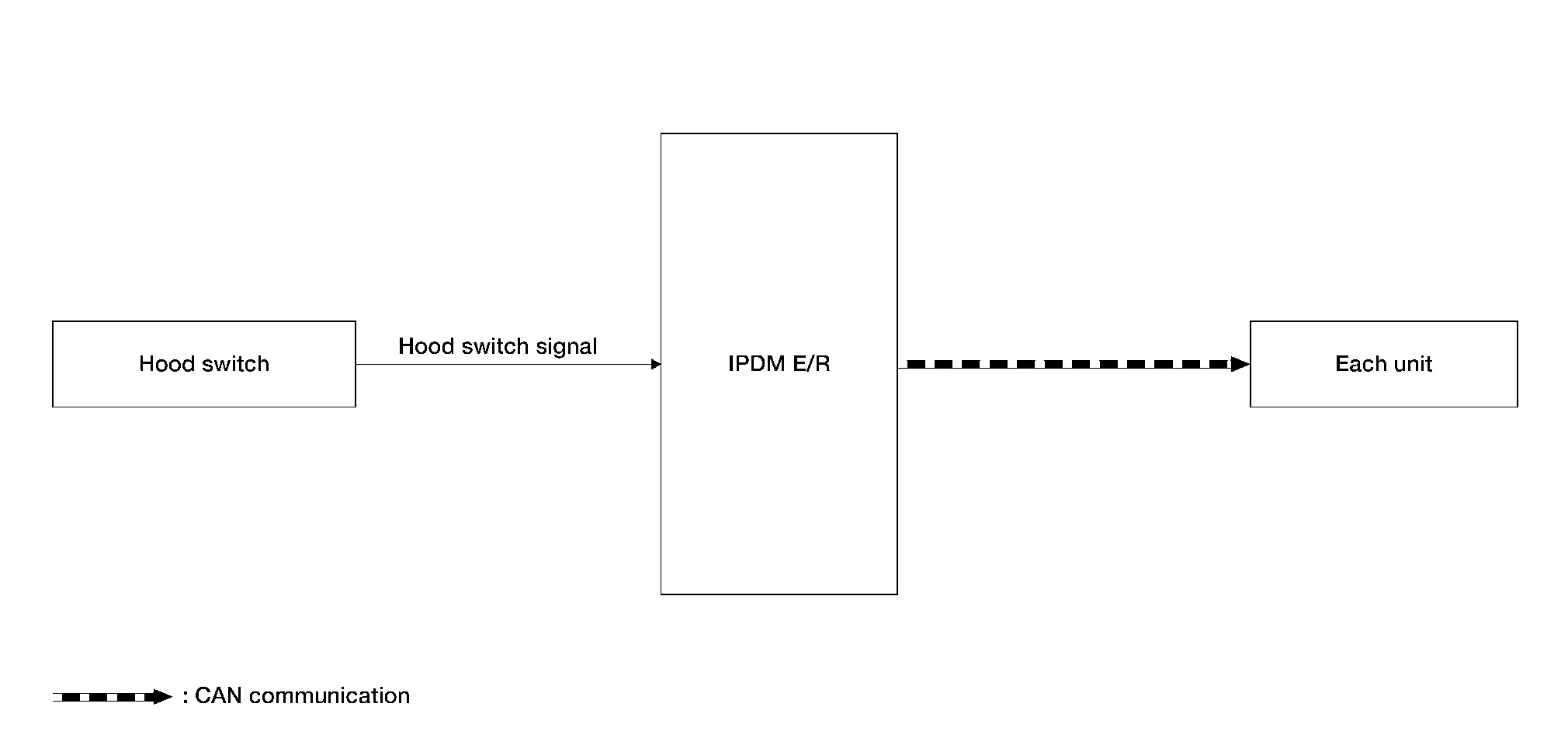
| Hood switch | Detects the hood condition (open or close), and inputs the hood switch signal to the IPDM E/R. |
| IPDM E/R | The IPDM E/R has the signal transmission function that transmits each input signal to each unit. |
Signal transmission function list
| Signal name | Input | Output | Description |
|---|---|---|---|
| Hood switch signal | Hood switch | Each unit (CAN) | Inputs the hood switch signal and transmits hood switch signal via CAN communication. |
Energy Managment System
System Description
SYSTEM DIAGRAM
| Component | Function | |
|---|---|---|
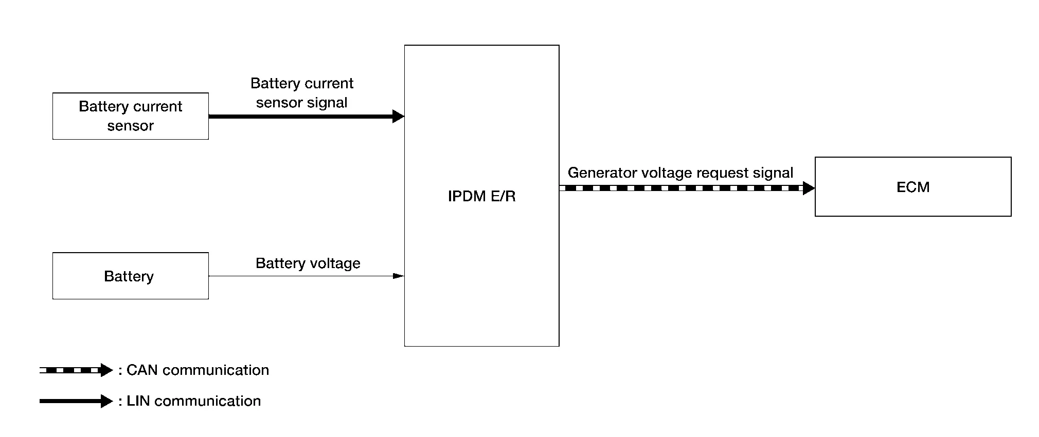
| Battery current sensor | Detects the charging/discharging current of the battery. | |
| Battery | Battery supplies power supply voltage to each unit and parts. | |
| IPDM E/R | The IPDM E/R transmits the generator voltage request signal to the ECM via CAN communication according to battery voltage and the battery temperature sensor signal. | |
| ECM | The ECM controls power generation voltage to the generator according to the request from the IPDM E/R received via CAN communication. | |
Signal transmission function list
| Signal name | Input | Output | Description |
|---|---|---|---|
| Battery current sensor signal | Battery current sensor | IPDM E/R (LIN) | Transmits the battery current sensor signal to the IPDM E/R via LIN communication. |
| Generator voltage request signal | IPDM E/R | ECM (CAN) | Transmits the generator voltage request signal via CAN communication. |
SYSTEM DESCRIPTION
The IPDM E/R has an energy management system that recognizes the battery status from the battery current sensor signal from the battery current sensor and battery voltage from the battery and maintains normal battery status. Refer to the following for details:
-
Charging system: Refer to System Description.
Diagnosis System (ipdm E/r) Nissan Pathfinder 5th Gen
CONSULT Function (IPDM E/R)
APPLICATION ITEM
CONSULT performs the following functions via CAN communication with IPDM E/R:
| Diagnosis mode | Description |
|---|---|
| Self Diagnostic Result | Displays non-network DTC which the IPDM E/R memorizes. |
| Data Monitor | Displays the real-time input/output data from the IPDM E/R input/output data. |
| Work Support | Changes the setting for each setting function. |
| Active Test | The IPDM E/R can provide a drive signal to electronic components to check their operations. |
| ECU Identification | Allows confirmation of the IPDM E/R part number. |
| Configuration | Read and save Nissan Pathfinder vehicle specification. |
| Network-DTC* | Displays network DTC which the IPDM E/R memorizes when performing "Diagnosis (All System)". |
*: Displays when performing "Diagnosis (All System)".
SELF DIAGNOSTIC RESULT
Refer to DTC Index.
DATA MONITOR
 NOTE:
NOTE:
The following table includes information (items) inapplicable to this Nissan Pathfinder vehicle. For information (items) applicable to this vehicle, refer to CONSULT display items.
| Monitor item | Description |
|---|---|
|
Compressor request 1 [Off/On] |
Displays the status of A/C compressor request signal received from ECM via CAN communication. |
|
Easy fill tire alert horn req [Off/On] |
This item is indicated, but not monitored. |
|
Cranking enable-TCM [Unknown/Prohibit/Permit/Stop] |
Displays the status of cranking enable signal received from TCM via CAN communication. |
|
Cranking enable-ECM [Prohibit/Permit/Stop/No req] |
Displays the status of cranking enable signal received from ECM via CAN communication. |
|
DTRL REQ [Off/On] |
Displays the status of daytime running light request signal received from BCM via CAN communication. |
|
COOLING FAN REQ [%] |
Displays the status of cooling fan speed request signal received from BCM via CAN communication. |
|
FR WIPER REQ [NG/HIGH/LOW/STOP/RETURN] |
Displays the status of front wiper request signal received from BCM via CAN communication. |
|
HIGH BEAM REQ [Off/On] |
Displays the status of high beam request signal received from BCM via CAN communication. |
|
Horn request [No req/Off/Panic/Hrn chirp/Thft warn/Return/Unknown] |
This item is indicated, but not monitored. |
|
Low beam request [Off/On] |
Displays the status of low beam request signal received from BCM via CAN communication. |
|
POSITION LIGHT REQ [Off/On] |
Displays the status of position light request signal received from BCM via CAN communication. |
|
IGNITION SW [Off/No request/On/START] |
Displays the status of ignition switch ON signal received from BCM via CAN communication. |
|
FRONT FOG LAMP REQ [Off/On] |
Displays the status of front fog light request signal received from BCM via CAN communication.
This item is monitored only on the Nissan Pathfinder vehicle with front fog lamp. |
|
Shift position [NG/M/D/N/R/P] |
Displays the status of shift position signal received from TCM via CAN communication. |
|
COMP ECV STATUS [NG/OK] |
Displays the status of compressor (ECV) malfunction diagnosis that IPDM E/R transmits via CAN communication. |
|
BATTERY VOLTAGE [V] |
Displays the status of battery voltage value that IPDM E/R transmits via CAN communication. |
|
Stop/start status [-] |
Indicates condition of start/stop system. |
|
FR WIPER STOP POSITION [ACTIVE P/STOP P] |
Displays the status of front wiper stop position signal that IPDM E/R transmits via CAN communication. |
|
IGNITION POWER SUPPLY [Off/On] |
This item is indicated, but not monitored. |
|
HOOD SW (CAN) [NG/OPEN/CLOSE] |
Displays the status of hood switch signal that IPDM E/R transmits via CAN communication.
This item is monitored only on the Nissan Pathfinder vehicle with stop/start system. |
|
A/C RELAY [Off/On] |
Displays the status of A/C compressor (magnetic clutch) output that IPDM E/R transmits via CAN communication. |
|
REVERSE SIGNAL (CAN) [NG/On/Off] |
Displays the status of reverse position signal that IPDM E/R transmits via CAN communication. |
|
COMP ECV CURRENT [A] |
Displays the status of electric current output to compressor (ECV) that IPDM E/R transmits via CAN communication. |
|
Starter&starter cont relay stat [Off, Off/On, Off/invalid/On, On] |
Displays the status of starter relay and starter control relay that IPDM E/R transmits via CAN communication. |
|
Hood switch [Open/Close] |
Displays the status of hood switch judged by IPDM E/R.
This item is monitored only on the Nissan Pathfinder vehicle with remote engine start system. |
|
IGN RELAY [Open/Close] |
Displays the status of ignition relay judged by IPDM E/R. |
|
Cooling fan relay-2 [OFF/ON] |
Displays the cooling fan relay drive status judged by IPDM E/R. |
|
Compressor [OFF/ON] |
Displays the A/C compressor (magnetic clutch) output status judged by IPDM E/R. |
|
Front wiper HI/LO relay [OFF/ON] |
Displays the front wiper high relay drive status judged by IPDM E/R. |
|
Horn relay [OFF/ON] |
This item is indicated, but not monitored. |
|
Front wiper relay [OFF/ON] |
Displays the front wiper relay drive status judged by IPDM E/R. |
|
Battery current sen value (LIN) [A] |
Displays the status of battery current value received from battery current sensor via LIN communication. |
|
Headlamp warning (LH) (LIN) [Open/Close] |
Displays the status of low beam LH malfunction received from LED headlamp control module LH via LIN communication. |
|
Headlamp warning (RH) (LIN) [Open/Close] |
Displays the status of low beam RH malfunction received from LED headlamp control module RH via LIN communication. |
|
Compressor ECV duty [%] |
Displays the compressor (ECV) output (PWM) status of IPDM E/R. |
|
Cooling fan relay-3 [%] |
Displays the cooling fan relay output (PWM) status of IPDM E/R. |
|
Front fog lamp (LH) [%] |
Displays the front fog lamp LH output (PWM) status of IPDM E/R.
This item is monitored only on the Nissan Pathfinder vehicle with front fog lamp. |
|
Front fog lamp (RH) [%] |
Displays the front fog lamp RH output (PWM) status of IPDM E/R.
This item is monitored only on the Nissan Pathfinder vehicle with front fog lamp. |
|
Tail lamp (LH) [%] |
Displays the tail lamp LH output (PWM) status of IPDM E/R. |
|
Tail lamp (RH) [%] |
Displays the tail lamp RH output (PWM) status of IPDM E/R. |
|
Headlamp LO (RH) [%] |
Displays the headlamp (LO) RH output (PWM) status of IPDM E/R. |
|
Headlamp LO (LH) [%] |
Displays the headlamp (LO) LH output (PWM) status of IPDM E/R. |
|
Parking lamp (LH) req (LIN) [Close/Open] |
Displays the status of parking lamp LH ON/OFF control that IPDM E/R transmits via LIN communication. |
|
DTRL (LH) req (LIN) [Close/Open] |
Displays the status of daytime running light LH ON/OFF control that IPDM E/R transmits via LIN communication. |
|
Headlamp LO (LH) req (LIN) [Close/Open] |
Displays the status of headlamp LO (LH) ON/OFF control that IPDM E/R transmits via LIN communication. |
|
Headlamp HI (LH) req (LIN) [Close/Open] |
Displays the status of headlamp HI (LH) ON/OFF control that IPDM E/R transmits via LIN communication. |
|
Parking lamp (RH) req (LIN) [Close/Open] |
Displays the status of parking lamp RH ON/OFF control that IPDM E/R transmits via LIN communication. |
|
DTRL (RH) req (LIN) [Close/Open] |
Displays the status of daytime running light RH ON/OFF control that IPDM E/R transmits via LIN communication. |
|
Parking/DTRL (LH) output (LIN) [%] |
Displays the parking lamp/daytime running light LH control signal output (PWM) status that IPDM E/R transmits via LIN communication. |
|
Parking/DTRL (RH) output (LIN) [%] |
Displays the parking lamp/daytime running light RH control signal output (PWM) status that IPDM E/R transmits via LIN communication. |
|
Headlamp HI (RH) req (LIN) [Close/Open] |
Displays the status of headlamp HI (RH) ON/OFF control that IPDM E/R transmits via LIN communication. |
|
Headlamp LO (RH) req (LIN) [Close/Open] |
Displays the status of headlamp LO (RH) ON/OFF control that IPDM E/R transmits via LIN communication. |
|
Battery status [—] |
Indicates condition of battery. |
|
T LAMP LH CIRC MALFUNCTN [―] |
Monitor the number of times that the Smart FET in IPDM E/R reaches the retry upper limit of the tail lamp LH circuit.
When the number of tail lamp LH circuit retries count is 20, this item counts 1. |
|
NMB T LAMP LH CIRC RETRY [―] |
Monitor the number of times that the Smart FET in IPDM E/R permits the retry of the tail lamp LH circuit.
When the number of short circuits in the tail lamp LH circuit count is 5 and the ignition switch OFF to ON operation is detected, this item counts 1. |
|
Fr fog lamp (LH) circ malfunctn [―] |
Monitor the number of times that the Smart FET in IPDM E/R reaches the retry upper limit of the front fog lamp LH circuit.
|
|
T LAMP RH CIRC MALFUNCTN [―] |
Monitor the number of times that the Smart FET in IPDM E/R reaches the retry upper limit of the tail lamp RH circuit.
When the number of tail lamp RH circuit retries count is 20, this item counts 1. |
|
NMB T LAMP RH CIRC RETRY [―] |
Monitor the number of times that the Smart FET in IPDM E/R permits the retry of the tail lamp RH circuit.
When the number of short circuits in the tail lamp RH circuit count is 5 and the ignition switch OFF to ON operation is detected, this item counts 1. |
|
NMB T LAMP RH CIRC SHORT [―] |
Monitor the number of times that the Smart FET in IPDM E/R detects the over current of the tail lamp RH circuit. |
|
NMB F FOG LH CIRC RETRY [―] |
Monitor the number of times that the Smart FET in IPDM E/R permits the retry of the front fog lamp LH circuit.
|
|
NMB F FOG LH CIRC SHORT [―] |
Monitor the number of times that the Smart FET in IPDM E/R detects the over current of the front fog lamp LH circuit.
This item is monitored only on the Nissan Pathfinder vehicle with front fog lamp. |
|
F FOG RH CIRC MALFUNCTN [―] |
Monitor the number of times that the Smart FET in IPDM E/R reaches the retry upper limit of the front fog lamp RH circuit.
|
|
NMB F FOG RH CIRC RETRY [―] |
Monitor the number of times that the Smart FET in IPDM E/R permits the retry of the front fog lamp RH circuit.
|
|
NMB F FOG RH CIRC SHORT [―] |
Monitor the number of times that the Smart FET in IPDM E/R detects the over current of the front fog lamp RH circuit.
This item is monitored only on the Nissan Pathfinder vehicle with front fog lamp. |
|
NMB T LAMP LH CIRC SHORT [―] |
Monitor the number of times that the Smart FET in IPDM E/R detects the over current of the tail lamp LH circuit. |
|
BAT DISCHARGE COUNT [―] |
Monitor the cumulative discharge value of the battery.
|
 NOTE:
NOTE:
 NOTE:
NOTE:
 NOTE:
NOTE:
 NOTE:
NOTE:
 NOTE:
NOTE:
 NOTE:
NOTE:
 NOTE:
NOTE:
 NOTE:
NOTE:
 NOTE:
NOTE:
 NOTE:
NOTE:
 NOTE:
NOTE:
 NOTE:
NOTE:
 NOTE:
NOTE:
 NOTE:
NOTE:
 NOTE:
NOTE:
 NOTE:
NOTE:
 NOTE:
NOTE:
 NOTE:
NOTE:
 NOTE:
NOTE:
 NOTE:
NOTE:
WORK SUPPORT
| Test item | Description |
|---|---|
| CML B/DCHRG CRNT CLEAR |
|
ACTIVE TEST
| Test item | Operation | Description |
|---|---|---|
| HORN | Off | OFF |
| On | Operates the horn relay for 20 ms. |
ECU IDENTIFICATION
The IPDM E/R part number is displayed.
CONFIGURATION
Refer to Description.

Nissan Pathfinder (R53) 2022-2026 Service Manual
System Description
Contact Us
Nissan Pathfinder Info Center
Email: info@nipathfinder.com
Phone: +1 (800) 123-4567
Address: 123 Pathfinder Blvd, Nashville, TN 37214, USA
Working Hours: Mon–Fri, 9:00 AM – 5:00 PM (EST)
