Nissan Pathfinder: Meter, Warning Lamp & Indicator - Dtc/circuit Diagnosis
- Meter/m&a (combination Meter) ➤
- E-Hud (head up Display Unit) ➤
- Power Supply and Ground Circuit
- Master Speaker Signal Circuit
- Steering Switch Signal a Circuit
- Steering Switch Signal B Circuit
- Illumination Control Switch Signal Circuit
- Fuel Level Sensor Signal Circuit
- Ambient Sensor Signal Circuit
- Head up Display Switch Signal Circuit
- Washer Fluid Level Switch Circuit
Meter/m&a (combination Meter) ➤ Nissan Pathfinder SUV
E-Hud (head up Display Unit) ➤ Nissan Pathfinder 2026
Power Supply and Ground Circuit Nissan Pathfinder SUV
Combination Meter
Diagnosis Procedure
CHECK FUSES
Check that the following fuses are not blown:
| Unit | Location | Fuse No. | Capacity |
|---|---|---|---|
| Combination meter | Fuse block (J/B) | 29 | 10A |
| 6 | 10A |
Is the fuse blown?
YES>>Replace the blown fuse after repairing the affected circuit.
NO>>GO TO 2.
CHECK POWER SUPPLY CIRCUIT
-
Disconnect combination meter harness connector.
-
Check voltage between combination meter harness connector and ground.
(+) (–) Ignition switch position Combination meter Connector Terminal OFF ON START M44 5 Ground Battery voltage Battery voltage Battery voltage 6 0V Battery voltage Battery voltage
Is the inspection result normal?
YES>>GO TO 3.
NO>>Repair or replace harness or connector.
CHECK GROUND CIRCUIT
-
Ignition switch OFF.
-
Check continuity between combination meter harness connector and ground.
Combination meter — Continuity Connector Terminal M44 7 Ground Yes
Is the inspection result normal?
YES>>Inspection End.
NO>>Repair or replace harness or connector.
Head up Display Unit
Diagnosis Procedure
CHECK FUSE
-
Ignition switch OFF.
-
Check that the following fuse is not blown:
Unit Location Fuse No. Capacity Head up display unit Fuse block (J/B) 48 10A
Is the fuse blown?
YES>>Replace the blown fuse after repairing the affected circuit.
NO>>GO TO 2.
CHECK HEAD UP DISPLAY UNIT POWER SUPPLY
-
Disconnect head up display unit harness connector.
-
Ignition switch ON.
-
Check the voltage between head up display unit harness connector and ground.
(+) (−) Voltage
(Approx.)Head up display unit Connector Terminal M107 9 Ground Battery voltage
Is the inspection result normal?
YES>>GO TO 4.
NO>>GO TO 3.
CHECK HEAD UP DISPLAY UNIT POWER SUPPLY CIRCUIT
-
Ignition switch OFF.
-
Check the continuity between head up display unit harness connector and fuse block (J/B) harness connector.
Head up display unit Fuse block (J/B) Continuity Connector Terminal Connector Terminal M107 9 M4 7C Yes
Is the inspection result normal?
YES>>GO TO 4.
NO>>Repair or replace harness or connector.
CHECK HEAD UP DISPLAY UNIT GROUND CIRCUIT
-
Ignition switch OFF.
-
Check the continuity between head up display unit harness connector and ground.
Head up display unit Ground Continuity Connector Terminal M107 16 Yes
Is the inspection result normal?
YES>>Inspection End.
NO>>Repair or replace harness or connector.
Master Speaker Signal Circuit Nissan Pathfinder
Diagnosis Procedure
CHECK MASTER SPEAKER CIRCUIT FOR OPEN
-
Ignition switch OFF.
-
Disconnect combination meter harness connector and master speaker harness connector.
-
Check the continuity between combination meter harness connector and master speaker harness connector.
Combination meter Master speaker Continuity Connector Terminal Connector Terminal M44 3 M276 1 Yes 4 4
Is the inspection result normal?
YES>>GO TO 2.
NO>>Repair or replace malfunctioning parts.
CHECK MASTER SPEAKER CIRCUIT FOR SHORT TO GROUND
Check the continuity between master speaker harness connector and ground.
| Master speaker | − | Continuity | |
|---|---|---|---|
| Connector | Terminal | ||
| M276 | 1 | Ground | No |
| 4 | |||
Is the inspection result normal?
YES>>GO TO 3.
NO>>Repair or replace malfunctioning parts.
CHECK MASTER SPEAKER CIRCUIT FOR SHORT TO POWER SUPPLY
-
Ignition switch ON.
-
Check the voltage between master speaker harness connector and ground.
| Master speaker | − |
Voltage (Approx.) | |
|---|---|---|---|
| Connector | Terminal | ||
| M276 | 1 | Ground | 0 V |
| 4 | |||
Is the inspection result normal?
YES>>Replace master speaker. Refer to Removal and Installation.
NO>>Repair or replace malfunctioning parts.
Steering Switch Signal a Circuit Nissan Pathfinder Fifth generation
Component Function Check
CHECK COMBINATION METER INPUT SIGNAL
 CONSULT
-
Ignition switch ON.
-
Select “STRG SW INPUT” in “Data Monitor” mode of “METER/M&A”.
-
Check that the function operates normally according to the following conditions:
| Monitor item | Condition | Status | |
|---|---|---|---|
| STRG SW INPUT | CONTROL switch | Pressed | SW1 |
| Scroll dial | Rotated upward | SW2 | |
| Scroll dial | Rotated downward | SW3 | |
| OK switch | Pressed | SW4 | |
| LEFT/BACK switch | Pressed | SW5 | |
| RIGHT switch | Pressed | SW6 | |
| VOL DOWN switch | Pressed | SW7 | |
| VOL UP switch | Pressed | SW8 | |
| TEL END switch | Pressed | SW9 | |
| VR/TEL switch | Pressed | SW10 | |
| SEEK DOWN switch | Pressed | SW11 | |
| SEEK UP switch | Pressed | SW12 | |
| Other than above | NO INPUT | ||
Is the inspection result normal?
YES>>Inspection End.
NO>>Refer to Diagnosis Procedure.
Diagnosis Procedure
The steering switch has a built-in CPU. Details for refer to Steering Switch.
CHECK FUSE
Check that the fuse is not blown:
| Unit | Location | Fuse No. | Capacity |
|---|---|---|---|
| Steering switches | Fuse block (J/B) | 40 | 10 A |
Is the fuse blown?
YES>>Replace the blown fuse after repairing the affected circuit.
NO>>GO TO 2.
CHECK STEERING SWITCH POWER SUPPLY CIRCUIT
-
Ignition switch ON.
-
Check voltage between spiral cable harness connector and ground.
(+) (−) Voltage
(Approx.)Spiral cable Connector Terminal M30 16 Ground Battery voltage
Is the inspection result normal?
YES>>GO TO 3.
NO>>Repair harness or connector.
CHECK STEERING SWITCH GROUND CIRCUIT
-
Ignition switch OFF.
-
Disconnect spiral cable harness connector.
-
Check continuity between spiral cable harness connector and ground.
Spiral cable Ground Continuity Connector Terminal M30 15 Yes
Is the inspection result normal?
YES>>GO TO 4.
NO>>Repair harness or connector.
CHECK STEERING SWITCH SIGNAL A CIRCUIT
-
Disconnect combination meter harness connector.
-
Check continuity between combination meter harness connector and spiral cable harness connector.
Combination meter Spiral cable Continuity Connector Terminal Connector Terminal M44 33 M30 13 Yes -
Check continuity between combination meter harness connector and ground.
Combination meter Ground Continuity Connector Terminal M44 33 No
Is the inspection result normal?
YES>>GO TO 5.
NO>>Repair harness or connector.
CHECK STEERING SWITCH SIGNAL GROUND CIRCUIT
-
Check continuity between combination meter harness connector and spiral cable harness connector.
Combination meter Spiral cable Continuity Connector Terminal Connector Terminal M44 34 M30 11 Yes -
Check continuity between combination meter harness connector and ground.
Combination meter Ground Continuity Connector Terminal M44 34 No
Is the inspection result normal?
YES>>GO TO 6.
NO>>Repair harness or connector.
CHECK SPIRAL CABLE
-
Disconnect spiral cable harness connectors.
-
Check continuity between spiral cable harness connectors.
| Spiral cable | Continuity | |||
| Connector | Terminal | Connector | Terminal | |
| M149 | 22 | M30 | 16 | Yes |
| 29 | 15 | |||
| 27 | 13 | |||
| 25 | 11 | |||
Is the inspection result normal?
YES>>GO TO 7.
NO>>Replace spiral cable. Refer to Removal and Installation.
CHECK STEERING SWITCH
Check steering switch. Refer to Component Inspection.
Is the inspection result normal?
YES>>Inspection End.
NO>>Replace steering switches. Refer to Removal and Installation.
Component Inspection
CHECK STEERING SWITCH RESISTANCE
-
Ignition switch OFF.
-
Disconnect spiral cable connector M149.
-
Check resistance between the following terminals:
| Spiral cable connector M149 | Condition |
Resistance Ω (Approx.) | |
|---|---|---|---|
| Terminal | Terminal | ||
| 27 | 25 | Depress CONTROL switch. | 1 |
Depress
 switch. switch. |
51 | ||
Depress
 switch. switch. |
133 | ||
| Depress OK switch. | 263 | ||
| Depress LEFT/BACK switch. | 653 | ||
| Depress RIGHT switch. | 2123 | ||
| 23 | Depress

 switch. switch. |
1 | |
Depress

 switch. switch. |
51 | ||
Depress
 switch. switch. |
133 | ||
Depress
 switch. switch. |
263 | ||
| Depress SEEK DOWN switch. | 653 | ||
| Depress SEEK UP switch. | 2123 | ||
Is the inspection result normal?
YES>>Inspection End.
NO>>Replace steering switch. Refer to Removal and Installation.
Steering Switch Signal B Circuit Nissan Pathfinder
Component Function Check
CHECK COMBINATION METER INPUT SIGNAL
 CONSULT
-
Ignition switch ON.
-
Select “STRG SW INPUT” in “Data Monitor” mode of “METER/M&A”.
-
Check that the function operates normally according to the following conditions:
| Monitor item | Condition | Status | |
|---|---|---|---|
| STRG SW INPUT | CONTROL switch | Pressed | SW1 |
| Scroll dial | Rotated upward | SW2 | |
| Scroll dial | Rotated downward | SW3 | |
| OK switch | Pressed | SW4 | |
| LEFT/BACK switch | Pressed | SW5 | |
| RIGHT switch | Pressed | SW6 | |
| VOL DOWN switch | Pressed | SW7 | |
| VOL UP switch | Pressed | SW8 | |
| TEL END switch | Pressed | SW9 | |
| VR/TEL switch | Pressed | SW10 | |
| SEEK DOWN switch | Pressed | SW11 | |
| SEEK UP switch | Pressed | SW12 | |
| Other than above | NO INPUT | ||
Is the inspection result normal?
YES>>Inspection End.
NO>>Refer to Diagnosis Procedure.
Diagnosis Procedure
CHECK STEERING SWITCH SIGNAL B CIRCUIT
-
Disconnect combination meter harness connector and spiral cable harness connector.
-
Check continuity between combination meter harness connector and spiral cable harness connector.
Combination meter Spiral cable Continuity Connector Terminal Connector Terminal M44 23 M30 9 Yes -
Check continuity between combination meter harness connector and ground.
Combination meter Ground Continuity Connector Terminal M44 23 No
Is the inspection result normal?
YES>>GO TO 2.
NO>>Repair harness or connector.
CHECK STEERING SWITCH SIGNAL GROUND CIRCUIT
-
Check continuity between combination meter harness connector and spiral cable harness connector.
Combination meter Spiral cable Continuity Connector Terminal Connector Terminal M44 34 M30 11 Yes -
Check continuity between combination meter harness connector and ground.
Combination meter Ground Continuity Connector Terminal M44 34 No
Is the inspection result normal?
YES>>GO TO 3.
NO>>Repair harness or connector.
CHECK SPIRAL CABLE
-
Disconnect spiral cable harness connectors.
-
Check continuity between spiral cable harness connectors.
Spiral cable Continuity Connector Terminal Connector Terminal M149 23 M30 9 Yes 25 11
Is the inspection result normal?
YES>>GO TO 4.
NO>>Replace spiral cable. Refer to Removal and Installation.
CHECK STEERING SWITCH
Check steering switch. Refer to Component Inspection.
Is the inspection result normal?
YES>>Inspection End.
NO>>Replace steering switches. Refer to Removal and Installation.
Component Inspection
CHECK STEERING SWITCH RESISTANCE
-
Ignition switch OFF.
-
Disconnect spiral cable connector M149.
-
Check resistance between the following terminals:
| Spiral cable connector M149 | Condition |
Resistance Ω (Approx.) | |
|---|---|---|---|
| Terminal | Terminal | ||
| 27 | 25 | Depress CONTROL switch. | 1 |
Depress
 switch. switch. |
51 | ||
Depress
 switch. switch. |
133 | ||
| Depress OK switch. | 263 | ||
| Depress LEFT/BACK switch. | 653 | ||
| Depress RIGHT switch. | 2123 | ||
| 23 | Depress

 switch. switch. |
1 | |
Depress

 switch. switch. |
51 | ||
Depress
 switch. switch. |
133 | ||
Depress
 switch. switch. |
263 | ||
| Depress SEEK DOWN switch. | 653 | ||
| Depress SEEK UP switch. | 2123 | ||
Is the inspection result normal?
YES>>Inspection End.
NO>>Replace steering switch. Refer to Removal and Installation.
Illumination Control Switch Signal Circuit Nissan Pathfinder SUV
Diagnosis Procedure
CHECK COMBINATION METER INPUT SIGNAL
-
Ignition switch ON.
-
Check voltage between the following terminals of the illumination control switch.
Illumination control switch Condition Voltage
(Approx.)Connector Terminals (+) (−) M113 6 4 When illumination control switch (+) is pressed 0 V Other than the above 5 V 7 When illumination control switch (−) is pressed 0 V Other than the above 5 V
Is the inspection result normal?
YES>>Inspection End.
NO>>GO TO 2.
CHECK ILLUMINATION CONTROL SWITCH SIGNAL CIRCUIT
-
Ignition switch OFF.
-
Disconnect combination meter harness connector and illumination control switch harness connector.
-
Check continuity between combination meter harness connector and illumination control switch harness connector.
Combination meter Illumination control switch Continuity Connector Terminal Connector Terminal M44 32 M113 4 Yes 31 7 25 6 -
Check continuity between combination meter harness connector and ground.
Combination meter — Continuity Connector Terminal M44 32 Ground No 31 25
Is the inspection result normal?
YES>>GO TO 3.
NO>>Repair or replace harness or connector.
CHECK ILLUMINATION CONTROL SWITCH
Check illumination control switch. Refer to Component Inspection.
Is the inspection result normal?
YES>>Replace combination meter. Refer to Removal and Installation.
NO>>Replace illumination control switch. Refer to Removal and Installation.
Component Inspection
CHECK ILLUMINATION CONTROL SWITCH
-
Ignition switch OFF.
-
Disconnect illumination control switch harness connector.
-
Check continuity between the following terminals of the illumination control switch:
Illumination control switch Condition Continuity Terminals 6 4 When illumination control switch (+) is pressed Yes Other than the above No 7 When illumination control switch (−) is pressed Yes Other than the above No
Is the inspection result normal?
YES>>Inspection End.
NO>>Replace illumination control switch. Refer to Removal and Installation.
Fuel Level Sensor Signal Circuit Nissan Pathfinder 5th Gen
Diagnosis Procedure
CHECK HARNESS CONNECTOR
-
Ignition switch OFF.
-
Check combination meter and fuel level sensor unit and fuel pump (fuel level sensor) terminals (meter-side and harness-side) for poor connection.
Is the inspection result normal?
YES>>GO TO 2.
NO>>Repair or replace harness or connector.
CHECK FUEL LEVEL SENSOR UNIT CIRCUIT
-
Disconnect combination meter harness connector and fuel level sensor unit and fuel pump (fuel level sensor) harness connector.
-
Check continuity between combination meter harness connector and fuel level sensor unit and fuel pump (fuel level sensor) harness connector.
Combination meter Fuel level sensor unit and fuel pump (fuel level sensor) Continuity Connector Terminal Connector Terminal M44 35 B57 3 Yes -
Check continuity between fuel level sensor unit and fuel pump (fuel level sensor) harness connector and ground.
Fuel level sensor unit and fuel pump (fuel level sensor) — Continuity Connector Terminal B57 3 Ground No
Is the inspection result normal?
YES>>GO TO 3.
NO>>Repair or replace harness or connector.
CHECK FUEL LEVEL SENSOR GROUND CIRCUIT
-
Check continuity between combination meter harness connector and fuel level sensor unit and fuel pump (fuel level sensor) harness connector.
Combination meter Fuel level sensor unit and fuel pump (fuel level sensor) Continuity Connector Terminal Connector Terminal M44 36 B57 2 Yes -
Check continuity between fuel level sensor unit and fuel pump (fuel level sensor) harness connector and ground.
Fuel level sensor unit and fuel pump (fuel level sensor) — Continuity Connector Terminal B57 2 Ground No
Is the inspection result normal?
YES>>GO TO 4.
NO>>Repair or replace harness or connector.
CHECK INSTALLATION CONDITION
Check fuel level sensor unit installation, and verify the float arm does not interfere or bind with the internal components in the fuel tank.
Is the inspection result normal?
YES>>Inspection End.
NO>>Install the fuel level sensor unit and fuel pump (fuel level sensor) properly. Refer to Removal and Installation.
Component Inspection
CHECK FUEL LEVEL SENSOR UNIT AND FUEL PUMP (FUEL LEVEL SENSOR)
-
Remove the fuel level sensor unit and fuel pump (fuel level sensor). Refer to Removal and Installation.
-
Check the resistance between fuel level sensor unit and fuel pump (fuel level sensor) terminals.
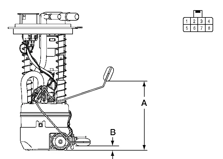
Fuel level sensor unit and fuel pump (fuel level sensor) Condition Resistance (Ω)
(Approx.)Height [in (mm)] Terminals 2 3 Full* (A) 91 5.95 (151.2) Empty* (B) 283.0 0.39 (10.1) *: When float rod is contact with stopper.
Is the inspection result normal?
YES>>Inspection End.
NO>>Replace fuel level sensor unit and fuel pump (fuel level sensor). Refer to Removal and Installation.
Ambient Sensor Signal Circuit Nissan Pathfinder R53
Diagnosis Procedure
CHECK AMBIENT SENSOR POWER SUPPLY
-
Ignition switch OFF.
-
Disconnect ambient sensor harness connector.
-
Ignition switch ON.
-
Check voltage between ambient sensor harness connector and ground.
(+) (–) Voltage
(Approx.)Ambient sensor Connector Terminal E206 1 Ground 5 V
Is the inspection result normal?
YES>>GO TO 2.
NO>>GO TO 4.
CHECK AMBIENT SENSOR GROUND CIRCUIT
-
Ignition switch OFF.
-
Check continuity between ambient sensor harness connector and ground.
Ambient sensor — Continuity Connector Terminal E206 2 Ground Yes
Is the inspection result normal?
YES>>GO TO 3.
NO>>Repair or replace harness or connector.
CHECK AMBIENT SENSOR
Check ambient sensor. Refer to Component Inspection.
Is the inspection result normal?
YES>>Replace combination meter. Refer to Removal and Installation.
NO>>Replace ambient sensor. Refer to Removal and Installation.
CHECK AMBIENT SENSOR POWER SUPPLY CIRCUIT FOR OPEN
-
Ignition switch OFF.
-
Disconnect combination meter harness connector.
-
Check continuity between ambient sensor harness connector and combination meter harness connector.
Ambient sensor Combination meter Continuity Connector Terminal Connector Terminal E206 1 M44 29 Yes
Is the inspection result normal?
YES>>GO TO 5.
NO>>Repair or replace harness or connector.
CHECK AMBIENT SENSOR POWER SUPPLY CIRCUIT FOR GROUND SHORT
Check continuity between ambient sensor harness connector and ground.
| Ambient sensor | — | Continuity | ||
|---|---|---|---|---|
| Connector | Terminal | |||
| E206 | 1 | Ground | No | |
Is the inspection result normal?
YES>>GO TO 6.
NO>>Repair or replace harness or connector.
CHECK AMBIENT SENSOR POWER SUPPLY CIRCUIT FOR POWER SHORT
-
Ignition switch ON.
-
Check voltage between ambient sensor harness connector and ground.
(+) (–) Voltage
(Approx.)Ambient sensor Connector Terminal E206 1 Ground 0 V
Is the inspection result normal?
YES>>Replace combination meter. Refer to Removal and Installation.
NO>>Repair or replace harness or connector.
Component Inspection
CHECK AMBIENT SENSOR
-
Ignition switch OFF.
-
Disconnect ambient sensor connector.
-
Check resistance between ambient sensor terminals.
Terminals Condition Resistance: kΩ Temperature: °C (°F) 1 2 −20 (−4) 16.50 −10 (14) 9.92 0 (32) 6.19 10 (50) 3.99 20 (68) 2.65 25 (77) 2.19 30 (86) 1.81 40 (104) 1.27
Is the inspection result normal?
YES>>Inspection End.
NO>>Replace ambient sensor. Refer to Removal and Installation.
Head up Display Switch Signal Circuit Nissan Pathfinder Fifth generation
Component Inspection
CHECK HEAD UP DISPLAY SWITCH
-
Ignition switch OFF.
-
Disconnect head up display switch connector.
-
Check head up display switch.
Head up display switch Condition Continuity Terminals 6 8 When the head up display switch is pressed Yes Other than above No
Is the inspection result normal?
YES>>Inspection End.
NO>>Replace head up display switch. Refer to Removal and Installation.
Washer Fluid Level Switch Circuit Nissan Pathfinder SUV
Diagnosis Procedure
CHECK WASHER FLUID LEVEL SWITCH SIGNAL CIRCUIT
-
Ignition switch OFF.
-
Disconnect combination meter harness connector and washer fluid level switch harness connector.
-
Check continuity between combination meter harness connector and washer fluid level switch harness connector.
Combination meter Washer fluid level switch Continuity Connector Terminal Connector Terminal M44 15 E208 2 Yes -
Check continuity between combination meter harness connector and ground.
Combination meter — Continuity Connector Terminal M44 15 Ground No
Is the inspection result normal?
YES>>GO TO 2.
NO>>Repair or replace harness or connectors.
CHECK WASHER FLUID LEVEL SWITCH GROUND CIRCUIT
Check continuity between washer fluid level switch harness connector and ground.
| Washer fluid level switch | — | Continuity | |
|---|---|---|---|
| Connector | Terminal | ||
| E208 | 1 | Ground | Yes |
Is the inspection result normal?
YES>>Inspection End.
NO>>Repair or replace harness or connectors.
Component Inspection
CHECK WASHER FLUID LEVEL SWITCH
-
Ignition switch OFF.
-
Disconnect washer fluid level switch connector.
-
Check washer fluid level switch.
Washer fluid level switch Condition Continuity Terminals 1 2 Washer fluid level switch ON Yes Washer fluid level switch OFF No
Is the inspection result normal?
YES>>Inspection End.
NO>>Replace washer fluid level switch. Refer to Removal and Installation.

Nissan Pathfinder (R53) 2022-2026 Service Manual
Dtc/circuit Diagnosis
- Meter/m&a (combination Meter) ➤
- E-Hud (head up Display Unit) ➤
- Power Supply and Ground Circuit
- Master Speaker Signal Circuit
- Steering Switch Signal a Circuit
- Steering Switch Signal B Circuit
- Illumination Control Switch Signal Circuit
- Fuel Level Sensor Signal Circuit
- Ambient Sensor Signal Circuit
- Head up Display Switch Signal Circuit
- Washer Fluid Level Switch Circuit
Contact Us
Nissan Pathfinder Info Center
Email: info@nipathfinder.com
Phone: +1 (800) 123-4567
Address: 123 Pathfinder Blvd, Nashville, TN 37214, USA
Working Hours: Mon–Fri, 9:00 AM – 5:00 PM (EST)
