Nissan Pathfinder: System Description - Component Parts ++
Automatic Air Conditioning System
Component Parts Location
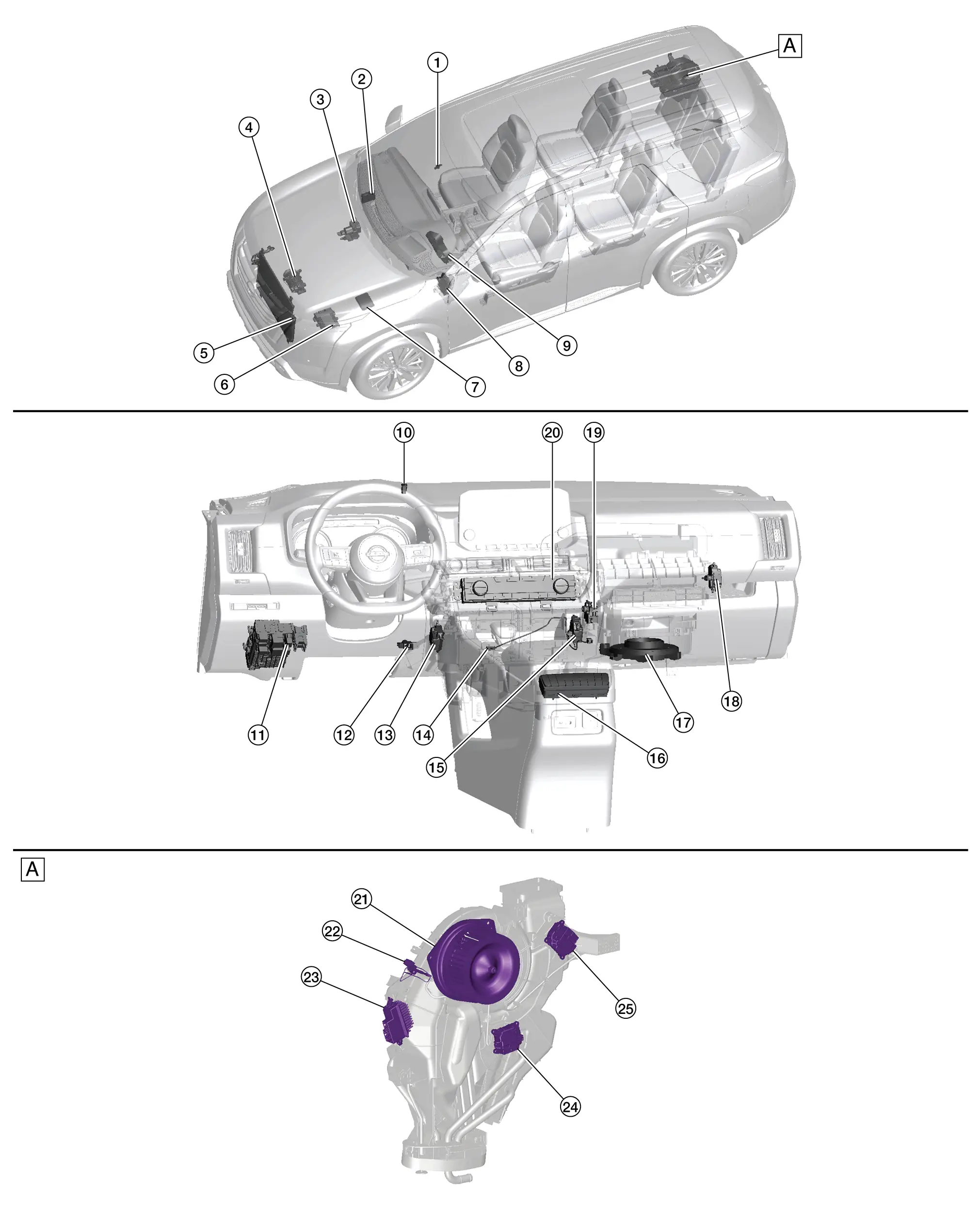
| A. | Right rear of vehicle (view with rear A/C and heater removed) |
| No. | Component | Function |
|---|---|---|
| 1. | Rain sensor (humidity sensor) | Refer to Rain Sensor (Humidity Sensor). |
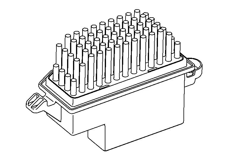
| 2. | A/C auto amp. | Refer to A/C Auto Amp.. |
| 3. | ABS (Anti-lock Braking System) actuator and electric unit (control unit) |
Transmits Nissan Pathfinder vehicle speed signal to A/C auto amp. via CAN communication. Refer to Component Parts Location for detailed component location. |
| 4. | A/C compressor | Refer to A/C Compressor. |
| 5. | Refrigerant pressure sensor | Refer to Refrigerant Pressure Sensor. |
| 6. | ECM (Engine Control Module) |
Sends an A/C compressor ON request to the IPDM E/R based on the status of engine operation and load as well as refrigerant pressure information. If all the conditions are met for A/C operation, the ECM transmits the A/C compressor ON request to the IPDM E/R. The ECM shares the refrigerant pressure sensor signal, engine RPM, and engine coolant temperature with the A/C auto amp. via CAN communication. Refer to Component Parts Location for detailed component location. |
| 7. | IPDM E/R (Intelligent Power Distribution Module Engine Room) |
Supply power to A/C compressor when A/C compressor request signal is received from ECM via CAN communication. Refer to System Description. |
| 8. | BCM (Body Control Module) |
Transmits remote engine start status signal to A/C auto amp. via CAN communication. Refer to System Description. |
| 9. | Combination meter |
Transmits ambient temperature signal to A/C auto amp. via CAN communication. Refer to Component Parts Location (Full TFT Meter) or Component Parts Location (7 Inch Information Display Meter) for detailed component location. |
| 10. | Sunload sensor | Refer to Sunload Sensor. |
| 11. | Fuse block (J/B) (heated steering wheel relay and back-up lamp relay) (if so equipped) | Supply the power to heated steering wheel. |
| 12. | Front in-Nissan Pathfinder vehicle sensor | Refer to Front In-Vehicle Sensor. |
| 13. | Air mix door motor LH | Refer to Air Mix Door Motor LH. |
| 14. | Intake sensor | Refer to Intake Sensor. |
| 15. | Air mix door motor RH | Refer to Air Mix Door Motor RH. |
| 16. | Rear A/C switch assembly (if so equipped) | Refer to Rear A/C Switch Assembly. |
| 17. | Front blower motor | Refer to Front Blower Motor. |
| 18. | Intake door motor | Refer to Intake Door Motor. |
| 19. | Mode door motor (front) | Refer to Mode Door Motor (Front). |
| 20. | Front A/C switch assembly | Refer to Front A/C Switch Assembly. |
| 21. | Rearblower motor | Refer to Rear Blower Motor. |
| 22. | Rear in-Nissan Pathfinder vehicle sensor | Refer to Rear In-Vehicle Sensor. |
| 23. | Rear blower motor resistor | Refer to Rear Blower Motor Resistor. |
| 24. | Air mix door motor (rear) (if so equipped) | Refer to Air Mix Door Motor (Rear). |
| 25. | Mode door motor (rear) (if so equipped) | Refer to Mode Door Motor (Rear). |
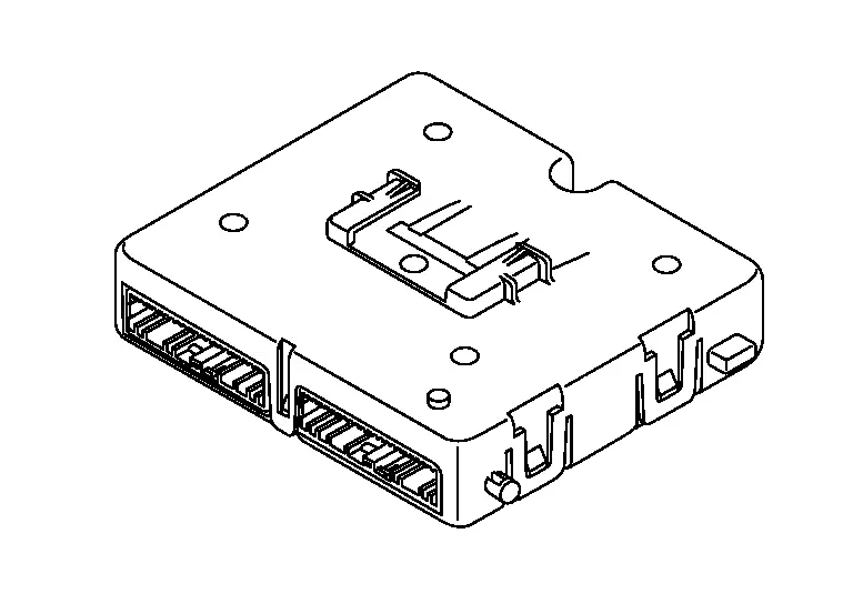
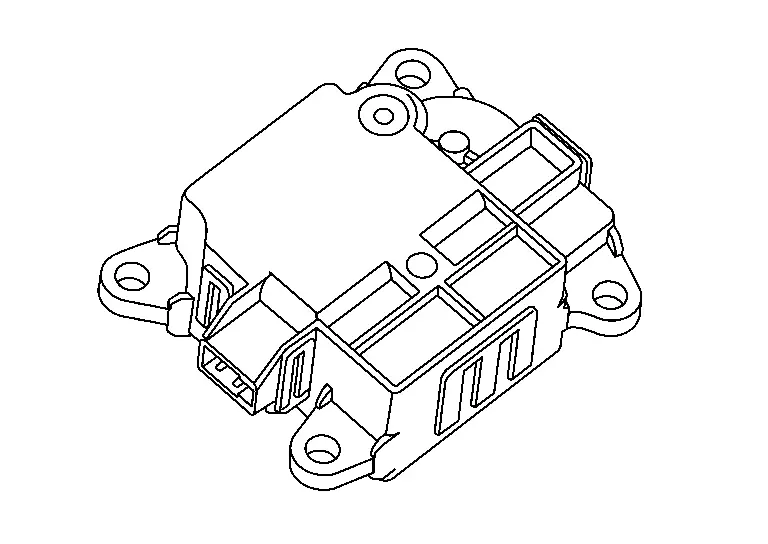
A/C Auto Amp.
-
The A/C auto amp. is installed to the blower unit assembly.
-
A/C auto amp. controls the automatic air conditioning system by inputting and calculating signals from each sensor and each switch.
-
The A/C auto amp. consists of a microcomputer and input/output connectors for signals and power supply.
-
It has a CAN communications function, and it transmits and receives the necessary signals from each control module via CAN communication.
-
It has a LIN communications function, and transmits and receives signals to/from the A/C switch assembly, each door motor, rear air control and each seat heater.
-
A/C auto amp. has self-diagnosis function. Diagnosis of automatic air conditioning system can be performed quickly.
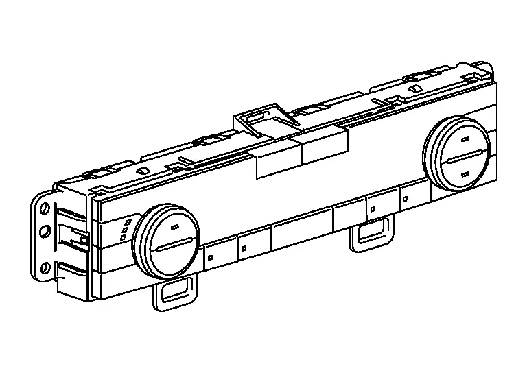
Front A/C Switch Assembly
-
The front A/C switch assembly is installed to the center ventilator finisher.
-
Front A/C switch assembly transmits setting status to A/C auto amp. via LIN communication. A/C auto amp. controls automatic air conditioning system.
-
Front A/C switch assembly has switches and display that can set and indicate the operation of automatic air conditioning system.
-
The conditions that are set for the automatic air conditioning system that is operated by each control switch are transmitted to the A/C auto amp. via LIN communication.
-
The operating status of the automatic air conditioner is transmitted from the A/C auto amp. via LIN communication.
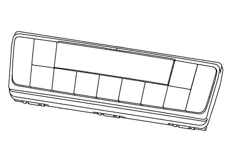
Rear A/C Switch Assembly
-
The rear A/C switch assembly is installed to the console rear finisher.
-
The rear A/C switch assembly is activated via LIN communication with the A/C auto amp., and can set the rear temperature.
-
The rear air conditioning operating status is indicated on the display located on the control.
-
The conditions that are set for the rear A/C switch assembly that is operated by temperature switch are transmitted to the A/C auto amp. via LIN communication.
-
The operating status of the air conditioner is transmitted from the A/C auto amp. via LIN communication.
-
The operation status of each switch is detected by the control and is transmitted as an operation signal to the A/C auto amp. via LIN communication.
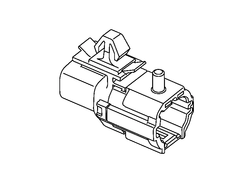
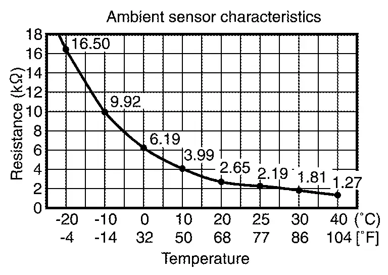
Ambient Sensor
-
The ambient sensor is installed to the active grille shutter.
-
The ambient sensor detects the temperature of the ambient air, and transmits the ambient sensor signal to the combination meter.
-
This signal is transmitted from the combination meter to the A/C auto amp. via CAN communication and is used in air conditioning system.
-
The ambient sensor measures the ambient air temperature.
-
The ambient sensor measures the ambient air temperature, and transmits the ambient sensor signal to the combination meter. This sensor uses a thermistor with electrical resistance that decreases as the temperature increases.
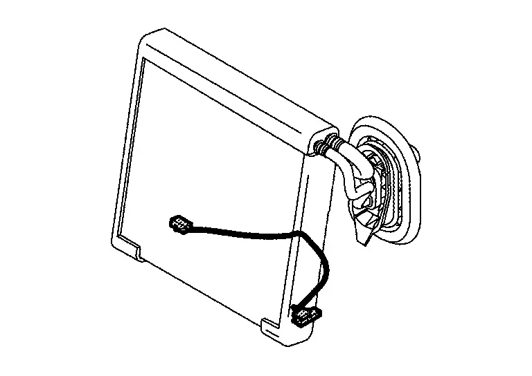
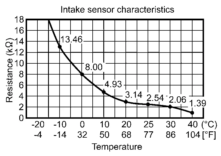
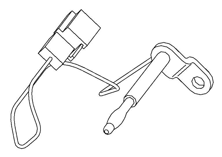
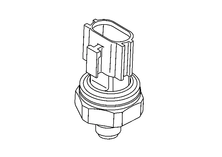
Intake Sensor
-
Intake sensor is located on the evaporator.
-
The intake sensor converts the evaporator surface temperature detected with thermistor into the voltage, and the A/C auto amp. inputs this voltage.
-
Intake sensor measures evaporator temperature (through air temperature).
-
The sensor uses a thermistor which is sensitive to the change in temperature. The electrical resistance of the thermistor decreases as temperature increases.
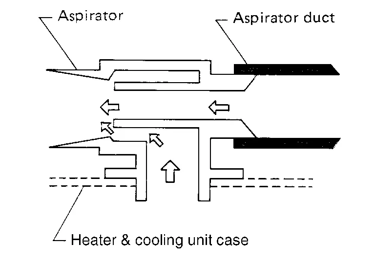
Front In-Vehicle Sensor
-
The front in-vehicle sensor is installed to the instrument lower panel LH.
-
The front in-Nissan Pathfinder vehicle sensor detects the temperature of the in-vehicle air that is taken in by the aspirator, and transmits the in-Nissan Pathfinder vehicle sensor signal to the A/C auto amp.
-
The front in-vehicle sensor measures the temperature of the in-Nissan Pathfinder vehicle air taken in by the front blower motor.
-
The front in-vehicle sensor measures the temperature of the in-Nissan Pathfinder vehicle air that is taken in by the aspirator, and transmits the in-vehicle sensor signal to the A/C auto amp. This sensor uses a thermistor with electrical resistance that decreases as the temperature increases.

-
 NOTE:
NOTE: The aspirator generates the vacuum by the air blown from the heating & cooling unit case and draws the air of the passenger room to the in-Nissan Pathfinder vehicle sensor area via the aspirator duct.
Rear In-Vehicle Sensor
-
The rear in-vehicle sensor is installed to the RH rear of the vehicle interior.
-
The rear in-Nissan Pathfinder vehicle sensor detects the temperature of the in-vehicle air that is taken in by the aspirator, and transmits the in-Nissan Pathfinder vehicle sensor signal to the A/C auto amp.
-
The rear in-vehicle sensor measures the temperature of the in-Nissan Pathfinder vehicle air taken in by the rear blower motor.
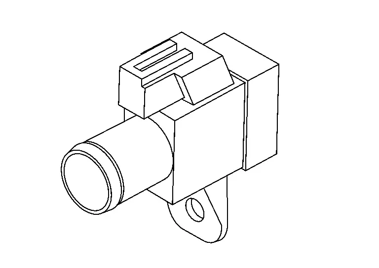
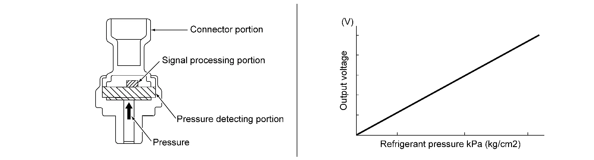
Refrigerant Pressure Sensor
-
The refrigerant pressure sensor is installed to the high pressure pipe.
-
The refrigerant pressure sensor converts high-pressure side refrigerant pressure into voltage and outputs it to ECM.
-
This value is transmitted from the ECM to the A/C auto amp. via CAN communication and is used in A/C compressor control and cooling fan operation request control.
-
The refrigerant pressure sensor converts refrigerant pressure into voltage.
-
The refrigerant pressure sensor is a capacitance type sensor. It consists of a pressure detection area and a signal processing area.
-
The pressure detection area, which is a variable capacity condenser, changes internal static capacitance according to pressure force.
-
The signal processing area detects the static capacitance of the pressure detection area, converts the static capacitance into a voltage value, and transmits the voltage value to ECM.
-
The output voltage increases as the refrigerant pressure rises.
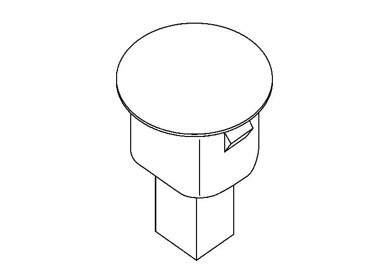
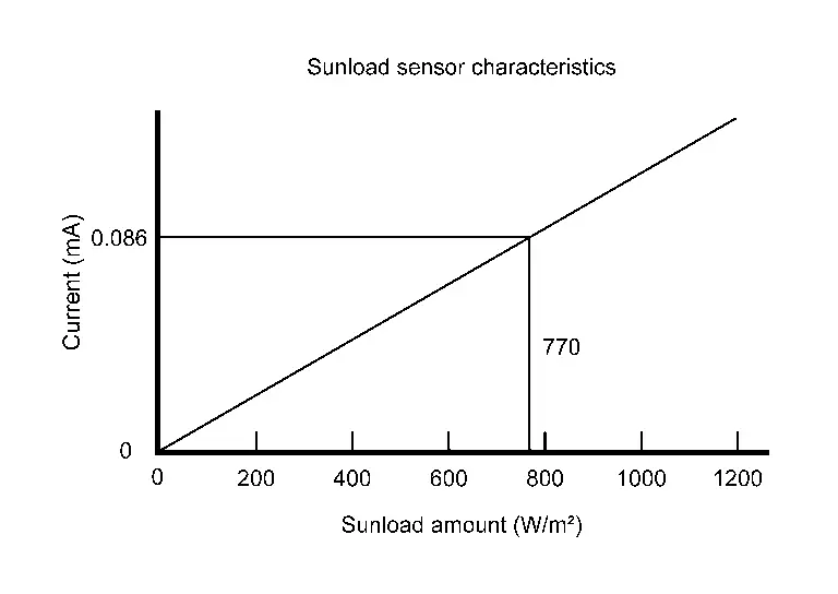
Sunlod Sensor
-
The sunload sensor is installed to the instrument garnish.
-
Sunload sensor converts sunload amount to voltage signal by photodiode and transmits to A/C auto amp.
-
Sunload sensor measures sunload amount.
-
The sunload sensor measures the sunload and outputs the sunload sensor signal to the A/C auto amp. This sensor uses a photodiode with an electrical current that increases as the sunload increases.
Air Mix Door Motor LH
-
The air mix door motor LH is installed to the heating & cooling unit assembly.

-
Air mix door motor LH consists of motor that drives door, PBR (Potentio Balance Register) that detects door position and LCU (Local Control Unit) that perform multiplex communication control (LIN) with A/C auto amp.
-
Rotation of motor is transmitted to front air mix door LH. Air flow temperature is switched.
-
LCU is built into air mix door motor LH. And detects door position by PBR.
-
A/C auto amp. communicates with each LCU via communication line. And receives air mix door LH position feedback signal from LCU.
-
LCU transmits the signal of door movement completion to A/C auto amp., when the door movement is completed.
Air Mix Door Motor RH
-
The air mix door motor RH is installed to the heating & cooling unit assembly.

-
Air mix door motor RH consists of motor that drives door, PBR (Potentio Balance Register) that detects door position and LCU (Local Control Unit) that perform multiplex communication control (LIN) with A/C auto amp.
-
Rotation of motor is transmitted to front air mix door RH. Air flow temperature is switched.
-
LCU is built into air mix door motor RH. And detects door position by PBR.
-
A/C auto amp. communicates with each LCU via communication line. And receives air mix door RH position feedback signal from LCU.
-
LCU transmits the signal of door movement completion to A/C auto amp., when the door movement is completed.
Air Mix Door Motor (Rear)
-
The air mix door motor (rear) is installed to the rear heating & cooling unit assembly.

-
Air mix door motor (rear) consists of motor that drives door, PBR (Potentio Balance Register) that detects door position and LCU (Local Control Unit) that perform multiplex communication control (LIN) with A/C auto amp.
-
Rotation of motor is transmitted to rear air mix door. Air flow temperature is switched.
-
LCU is built into air mix door motor (rear). And detects door position by PBR.
-
A/C auto amp. communicates with each LCU via communication line. And receives air mix door (rear) position feedback signal from LCU.
-
LCU transmits the signal of door movement completion to A/C auto amp., when the door movement is completed.
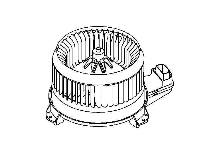
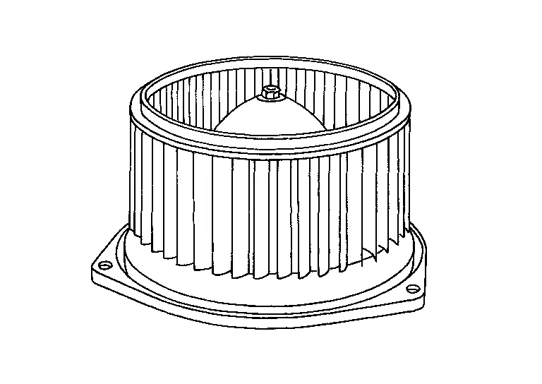
Front Blower Motor
-
The front blower motor is installed to the blower unit assembly.
-
The rotation speed is changed according to the voltage controlled by the A/C auto amp. and the air flow rate is controlled.
-
The front blower motor adopts the brush-less.
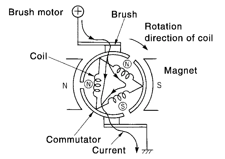
 NOTE:
NOTE: -
Brush motor rotates the coil while the brush functions as contact point.

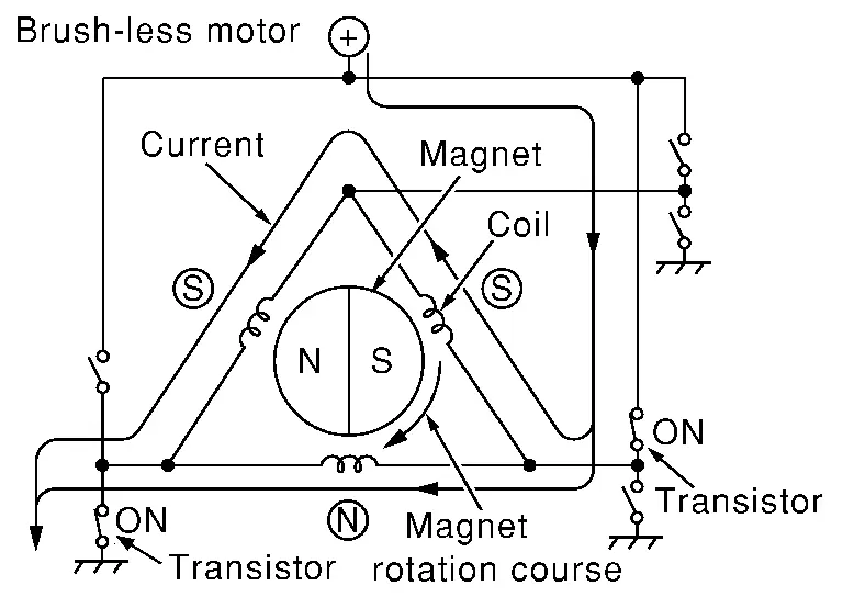
-
Brush-less motor, the magnet part rotates.

-
Rear Blower Motor
-
The rear blower motor is installed to the rear blower unit assembly.
-
The rotation speed is changed according to the voltage controlled by the A/C auto amp. and the air flow rate is controlled.
-
The rear blower motor adopts brushless technology.
 NOTE:
NOTE: -
Brush motor rotates the coil while the brush functions as contact point.
-
Brushless motor, the magnet part rotates.
-
Intake Door Motor
-
The intake door motor is installed to the blower unit assembly.

-
Intake door motor consists of motor that drives door, PBR (Potentio Balance Register) that detects door position and LCU (Local Control Unit) that perform multiplex communication control (LIN) with A/C auto amp.
-
Rotation of motor is transmitted to intake door. Air inlet is switched.
-
LCU is built into intake door motor. And detects door position by PBR.
-
A/C auto amp. communicates with each LCU via communication line. And receives intake door position feedback signal from LCU.
-
LCU transmits the signal of door movement completion to A/C auto amp., when the door movement is completed.
Mode Door Motor (Front)
-
The mode door motor is installed to the heating & cooling unit assembly.
-
Mode door motor (front) consists of motor that drives door, PBR (Potentio Balance Register) that detects door position and LCU (Local Control Unit) that perform multiplex communication control (LIN) with A/C auto amp.
-
Rotation of motor is transmitted to each mode door. Air outlet is switched.
-
LCU is built into mode door motor (front). And detects door position by PBR.
-
A/C auto amp. communicates with each LCU via communication line. And receives each mode door position feedback signal from LCU.
-
LCU transmits the signal of door movement completion to A/C auto amp., when the door movement is completed.
Mode Door Motor (Rear)
-
The mode door motor is installed to the rear heating & cooling unit assembly.

-
Mode door motor (rear) consists of motor that drives door, PBR (Potentio Balance Register) that detects door position and LCU (Local Control Unit) that perform multiplex communication control (LIN) with A/C auto amp.
-
Rotation of motor is transmitted to each mode door. Air outlet is switched.
-
LCU is built into mode door motor (rear). And detects door position by PBR.
-
A/C auto amp. communicates with each LCU via communication line. And receives each mode door position feedback signal from LCU.
-
LCU transmits the signal of door movement completion to A/C auto amp., when the door movement is completed.
A/C Compressor
-
The A/C compressor is installed to the engine.
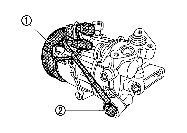
-
IPDM E/R controls the magnetic clutch and ECV (Electrical Control Valve) according to the requests from the A/C auto amp. and ECM, and changes the A/C compressor drive and refrigerant discharge amount.
-
For controlling the A/C compressor, a magnetic clutch
 that drives the A/C compressor is used, together with an ECV
  that changes the refrigerant discharge amount.
 -
Magnetic clutch consists of pulley, clutch disc, and field coil.
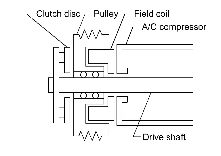
-
Pulley is connected with crankshaft pulley of engine via drive belt and is always rotated while engine is running.
-
Clutch disc is connected with drive shaft of A/C compressor.
-
Field coil, which becomes a strong electric magnet when electricity is supplied, strongly pulls clutch disc and presses it to pulley.
-
COMPONENT OPERATION
Magnetic Clutch
-
When smart FET (Field-Effect Transistor) integrated in IPDM E/R turns ON, electricity is supplied to field coil, clutch disc is presses to pulley, and engine rotational movement is transmitted from crankshaft pulley ⇒ drive belt ⇒ pulley ⇒ clutch disc ⇒ drive shaft. A/C compressor is operated. When smart FET turns OFF, electricity is not supplied to field coil, and clutch disc is released from pulley. A/C compressor is not operated.
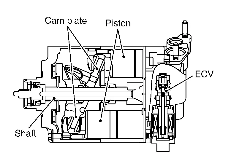
ECV (Electrical Control Valve)
-
ECV (Electrical Control Valve) is integrated in the A/C compressor. IPDM E/R receives the ECV control signal from A/C auto amp. via CAN communication, and ECV is controlled according to the control signal transmitted from IPDM E/R.
-
ECV is controlled according to the control signal transmitted from IPDM E/R.
The control signal transmitted by IPDM E/R is controlled according to the ECV control signal transmitted from A/C auto amp. via CAN communication.
-
ECV varies the refrigerant pressure balance in the left and right refrigerant spaces that are divided by the cam plate in order to change the angle of the cam plate inside the A/C compressor.
By changing the cam plate angle, it changes the piston stroke and controls the refrigerant discharge amount.
Rear Blower Motor Resistor
-
Rear blower motor resistor is installed on the rear blower unit assembly.
-
Rear blower motor resistor, that uses MOS field effect transistor, is adopted for rear blower motor speed control.
 NOTE:
NOTE: MOS field effect transistor is a transistor for which the gate portion is composed of a metal electrode on an oxide layer of semiconductor. Field effect transistor is controlled by voltage, while ordinary transistor is controlled by current. Electrode of field effect transistor is called source, drain, or gate, while electrode of ordinary transistor is called emitter, collector, or base.
-
Rear blower motor resistor continuously controls voltage to rear blower motor, according to gate voltage from A/C auto amp.
-
This rear blower motor resistor does not require a HI relay even when the maximum voltage is applied to rear blower motor at HI status, because voltage drop is nominal.
Rain Sensor (Humidity Sensor)
-
The rain sensor (humidity sensor) is installed on the windshield.
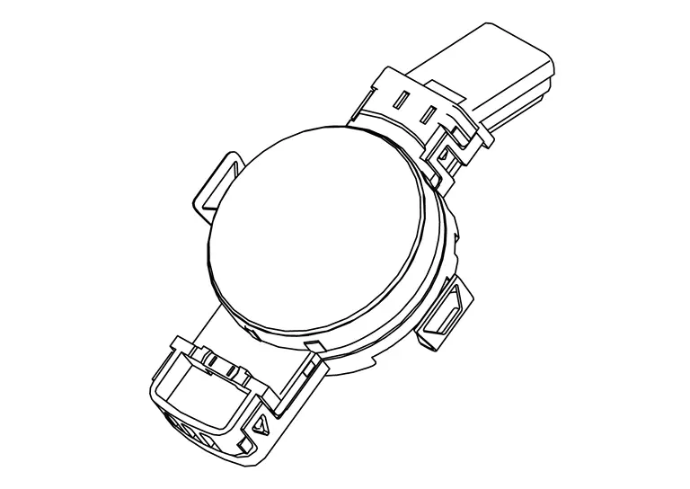
-
Detects and transmits the humidity level signal to the BCM.

Nissan Pathfinder (R53) 2022-2026 Service Manual
Contact Us
Nissan Pathfinder Info Center
Email: info@nipathfinder.com
Phone: +1 (800) 123-4567
Address: 123 Pathfinder Blvd, Nashville, TN 37214, USA
Working Hours: Mon–Fri, 9:00 AM – 5:00 PM (EST)
