Nissan Pathfinder: System Description - Component Parts ++
Brake Control System Component Parts Location
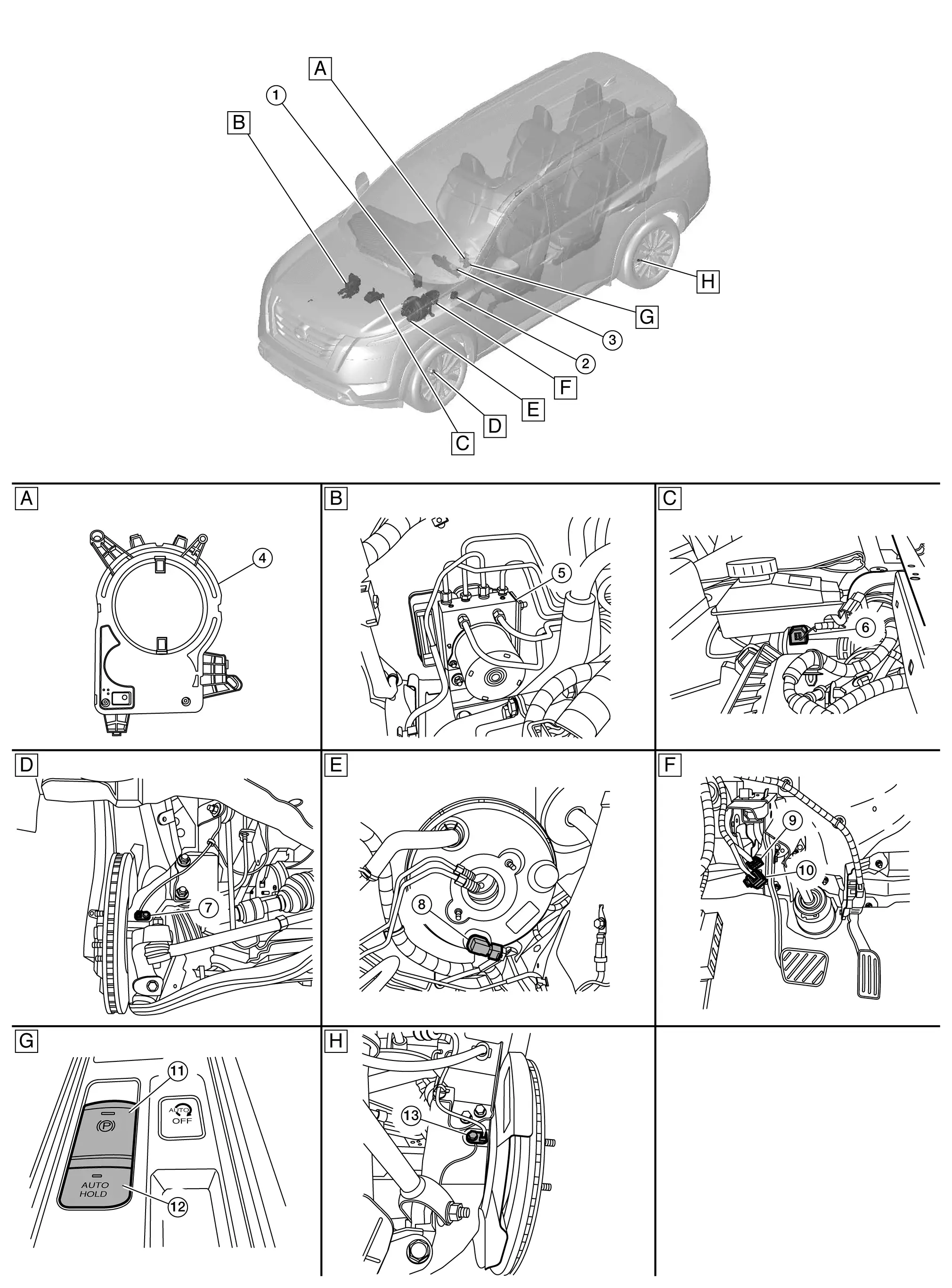
| A. | Steering column area | B. | Engine room (RH) | C. | Engine room (LH) |
| D. | Front left wheel | E. | Engine room (LH) | F. | Brake pedal area |
| G. | Center console area | H. | Rear left wheel | ||
| No. | Component | Function | |
|---|---|---|---|
| 1. | ADAS (Advanced Driver Assistance System) control unit 2 |
|
|
| 2. | Chassis control module |
Mainly transmits the following signals to ABS actuator and electric unit (control unit) via CAN communication:
|
|
| 3. | Combination meter |
Mainly transmits the following signals to ABS actuator and electric unit (control unit) via CAN communication:
Mainly receives the following signals from ABS actuator and electric unit (control unit) via CAN communication:
|
|
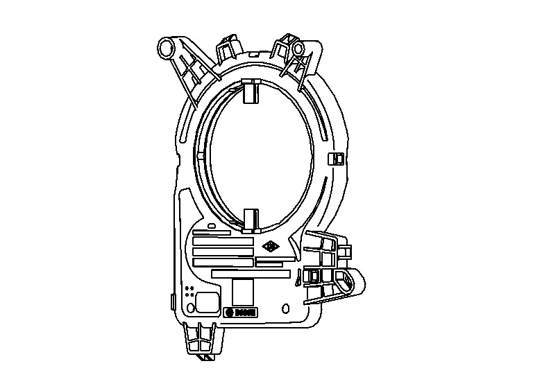
| 4. | Steering angle sensor |
Transmits the steering angle sensor malfunction signal to ADAS control unit 2, 4WD control unit, Chassis control unit ABS actuator and electric unit (control unit) and AV control unit via CAN communication. Refer to Steering Angle Sensor. |
|
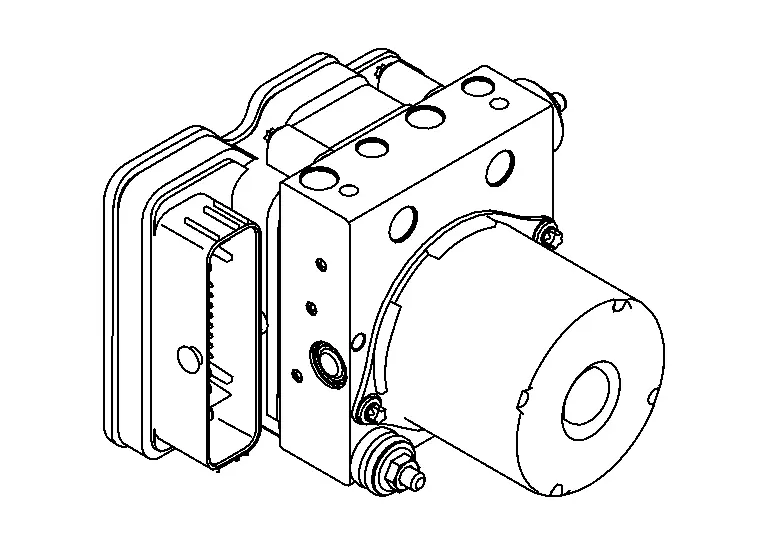
| 5. | ABS (Anti-lock Braking System) actuator and electric unit (control unit) | Refer to ABS Actuator and Electric Unit (Control Unit). | |
| 6. | Brake fluid level switch | Refer to Brake Fluid Level Switch. | |
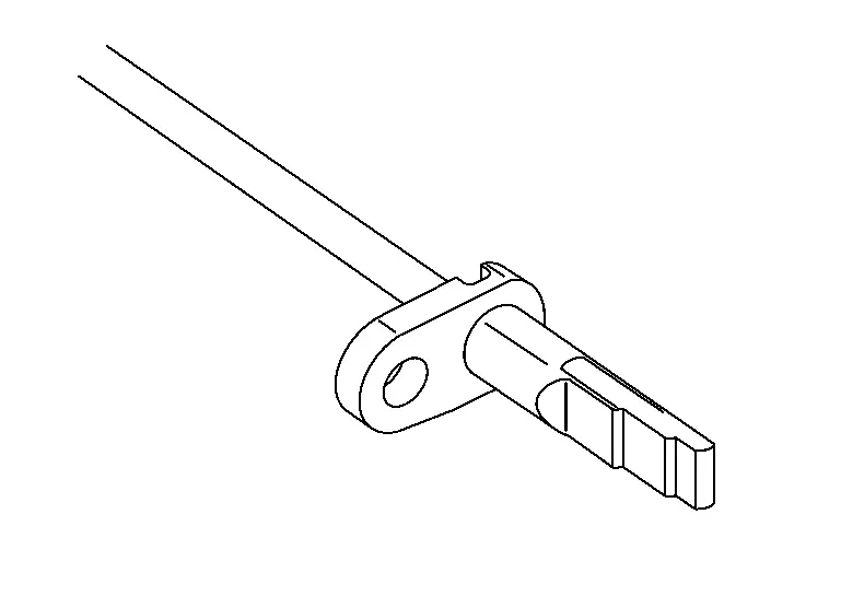
| 7. | Front wheel sensor LH (RH similar) | Refer to Wheel Sensor and Sensor Rotor. | |
| 8. | Vacuum sensor | Refer to Vacuum Sensor. | |
| 9. | Brake pedal position switch | Refer to Brake Pedal Position Switch. | |
| 10. | Stop lamp switch | Refer to Stop Lamp Switch. | |
| 11. | Electric parking brake switch | Refer to Component Parts Location. | |
| 12. | Auto brake hold switch | Refer to Component Parts Location. | |
| 13. | Rear wheel sensor LH (RH similar) | Refer to Wheel Sensor and Sensor Rotor. | |
ABS Actuator and Electric Unit (Control Unit)
FUNCTIONS WITHIN THE SYSTEM
Electric unit (control unit) is integrated with actuator and comprehensively controls VDC function, TCS function, ABS function, EBD function, Active brake limited slip (ABLS) function, Brake assist function, brake force distribution function, hill start assist function and electric parking brake function.
INDIVIDUAL FUNCTIONS WITHIN THE SYSTEM
ELECTRIC UNIT (CONTROL UNIT)
-
Brake fluid pressure, engine and transaxle are controlled according to signals from each sensor.
-
If a malfunction is detected, the system enters fail-safe mode.
ACTUATOR
The following components are integrated with ABS actuator.
Pump
-
Pressure the brake fluid and send.
-
Returns the brake fluid reserved in reservoir to master cylinder by reducing pressure.
Motor
Activates the pump according to signals from ABS actuator and electric unit (control unit).
Motor Relay
Operates the motor ON/OFF according to signals from ABS actuator and electric unit (control unit).
Actuator Relay
Operates each valve ON/OFF according to signals from ABS actuator and electric unit (control unit).
ABS In Valve
Switches the fluid pressure line to increase or hold according to signals from control unit.
 NOTE:
NOTE:
Valve is a solenoid valve.
ABS Out Valve
Switches the fluid pressure line to increase, hold or decrease according to signals from control unit.
 NOTE:
NOTE:
Valve is a solenoid valve.
Cut Valve 1, Cut Valve 2
Shuts off the ordinary brake line from master cylinder, when VDC function, TCS function, active brake limited slip (ABLS) function, brake assist function, brake force distribution function, and hill start assist function are activated.
 NOTE:
NOTE:
Valve is a solenoid valve.
Suction Valve 1, Suction Valve 2
Supplies the brake fluid from master cylinder to the pump, when VDC function, TCS function, active brake limited slip (ABLS) function, brake assist function, brake force distribution function, and hill start assist function are activated.
 NOTE:
NOTE:
Valve is a solenoid valve.
Inlet Valve
Brake fluid sucked from the reservoir by the pump does not backflow.
 NOTE:
NOTE:
Valve is a solenoid valve.
Outlet Valve
Brake fluid discharged from the pump does not backflow.
 NOTE:
NOTE:
Valve is a solenoid valve.
Return Check Valve
Returns the brake fluid from brake caliper to master cylinder by bypassing orifice of each valve when brake is released.
Reservoir
Temporarily reserves the brake fluid drained from brake caliper and wheel cylinder, so that pressure efficiently decreases when decreasing pressure of brake caliper.
Yaw Rate/Side/Decel G Sensor
Calculates the following information that affects the vehicle, and transmits a signal to ABS actuator and electric unit (control unit) via communication lines. [Yaw rate/side/decel G sensor is integrated in ABS actuator and electric unit (control unit).]
-
Vehicle rotation angular velocity (yaw rate signal)
-
Vehicle lateral acceleration (side G signal) and longitudinal acceleration (decel G signal)
Pressure Sensor
Detects the brake fluid pressure and transmits signal to ABS actuator and electric unit (control unit). [Pressure sensor is integrated in ABS actuator and electric unit (control unit).]
INDIVIDUAL OPERATION
-
Brake fluid pressure, and traction motor are controlled according to signals from each sensor.
-
If malfunction is detected, the system enters fail-safe mode.
PARTS LOCATION
Refer to Component Parts Location.
Wheel Sensor and Sensor Rotor
FUNCTIONS WITHIN THE SYSTEM
Wheel sensor and sensor rotor detect each wheel speed. And wheel sensor inputs wheel speed signal to ABS actuator and electric unit (control unit).
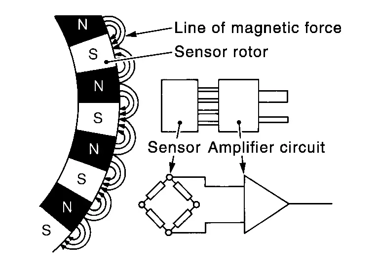
INDIVIDUAL FUNCTIONS WITHIN THE SYSTEM
The wheel sensor reads a magnetic field change.
INDIVIDUAL OPERATION
-
Downsize and weight reduction is aimed. IC for detection portion and magnet for sensor rotor are adopted.
-
Power supply is supplied to detection portion so that magnetic field line is read. Magnetic field that is detected is converted to current signal.
-
When sensor rotor rotates, magnetic field changes. Magnetic field change is converted to current signals (rectangular wave) and is transmitted to ABS actuator and electric unit (control unit). Change of magnetic field is proportional to wheel speed.
PARTS LOCATION
Refer to Component Parts Location.
Steering Angle Sensor
FUNCTIONS WITHIN THE SYSTEM
Steering angle sensor transmits steering angle sensor signal to ABS actuator and electric unit (control unit) via CAN communication.
INDIVIDUAL FUNCTIONS WITHIN THE SYSTEM
Steering angle sensor detects the following status.
-
Steering wheel rotation amount
-
Steering wheel rotation angular velocity
-
Steering wheel rotation direction
INDIVIDUAL OPERATION
Steering angle sensor converts the rotation amount, rotation angular velocity and rotation direction of the steering wheel as the steering angle sensor signal.
PARTS LOCATION
Refer to Component Parts Location.
Brake Fluid Level Switch
FUNCTIONS WITHIN THE SYSTEM
Detects the brake fluid level in reservoir tank and transmits converted electric signal from combination meter to ABS actuator and electric unit (control unit) via CAN communication, when brake fluid level is the specified level or less.
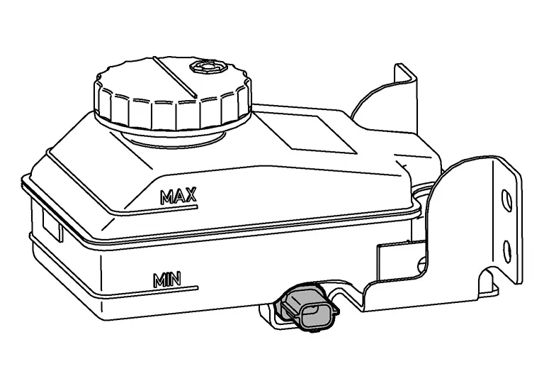
INDIVIDUAL FUNCTIONS WITHIN THE SYSTEM
Brake fluid level switch detects the brake fluid level in reservoir tank.
INDIVIDUAL OPERATION
-
The switch is turned ON when brake fluid level is the specified level or less.
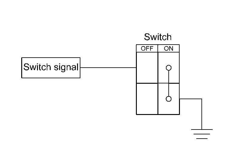
-
Ground is supplied as the switch signal to the control unit when the switch is ON.
PARTS LOCATION
Refer to Component Parts Location.
Brake Vacuum Sensor
FUNCTIONS WITHIN THE SYSTEM
Detects the vacuum in brake booster and transmits converted electric signal to ABS actuator and electric unit (control unit).
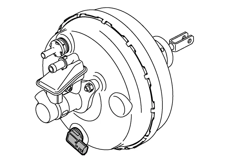
INDIVIDUAL FUNCTIONS WITHIN THE SYSTEM
Detects the vacuum in brake booster.
INDIVIDUAL OPERATION
Brake vacuum sensor converts the brake vacuum sensor signal.
PARTS LOCATION
Refer to Component Parts Location.
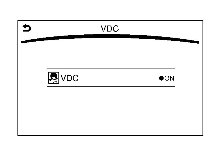
Integral Switch (VDC OFF signal)
-
Non-operational status or standby status of the following functions can be selected using VDC OFF. VDC OFF indicator indicates the operation status of function. (ON: Non-operational status, OFF: Standby status)
-
VDC function
-
TCS function
-
Active trace control function
-
 NOTE:
NOTE:
VDC OFF switch is a menu selection in the integral switch.
 NOTE:
NOTE:
ABS function and EBD function control operates.
-
VDC OFF indicator turns OFF (standby status) when the engine is started again after it is stopped once while VDC OFF indicator lamp is ON (non-operational status).

Nissan Pathfinder (R53) 2022-2026 Service Manual
Contact Us
Nissan Pathfinder Info Center
Email: info@nipathfinder.com
Phone: +1 (800) 123-4567
Address: 123 Pathfinder Blvd, Nashville, TN 37214, USA
Working Hours: Mon–Fri, 9:00 AM – 5:00 PM (EST)
