Nissan Pathfinder: Brake Control System - System Description
Component Parts Nissan Pathfinder 2022
Chassis Control System
Component Parts Location
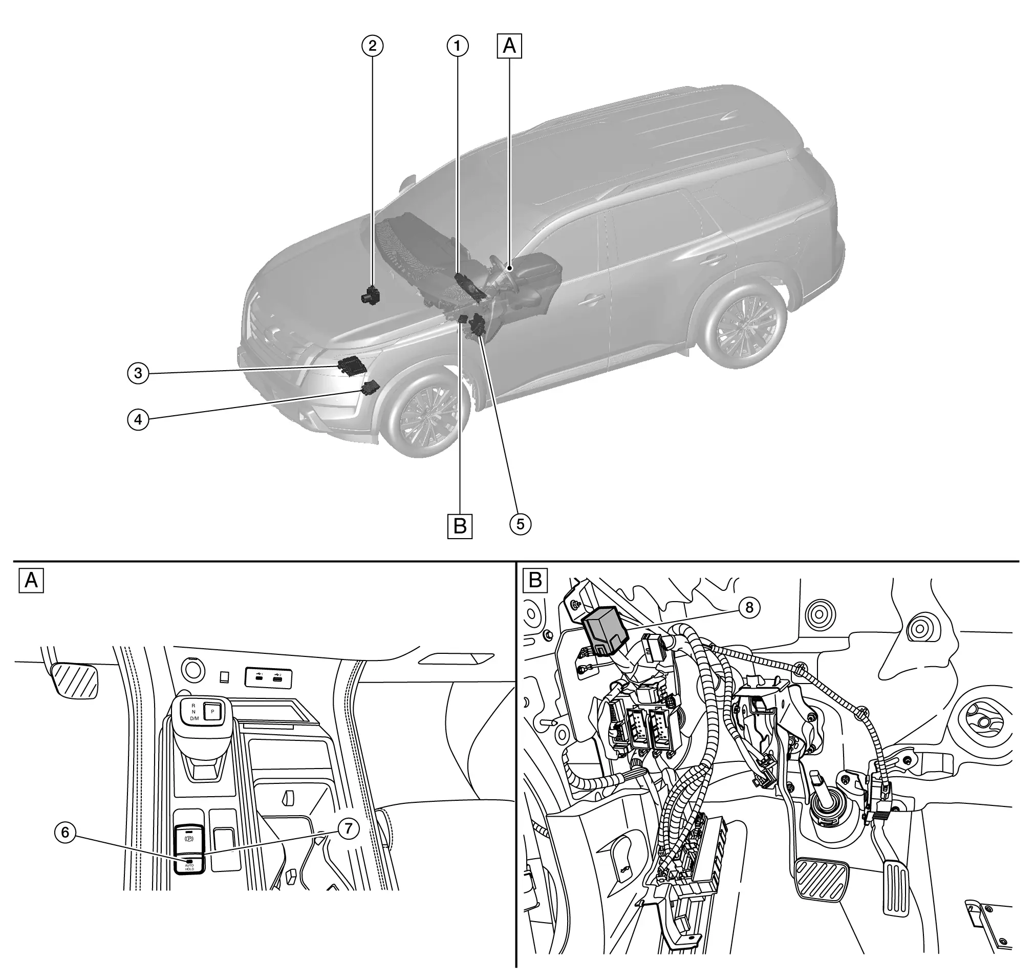
| A. | Center console finisher | B. | Upside of instrument lower panel LH |
| No. | Component | Function | |
|---|---|---|---|
| 1. | Combination meter | Refer toComponent Parts Location (7 inch information display) for detailed installation location. | |
| 2. | ABS (Anti-lock Braking System) actuator and electric unit (control unit) | Refer to Component Parts Location for detailed installation location. | |
| 3. | ECM (Engine Control Module) | Refer to Component Parts Location for detailed installation location. | |
| 4. | TCM (Transmission Control Module) | Refer to Component Parts Location for detailed installation location. | |
| 5. | BCM (Body Control Module) | Refer to Component Parts Location for detailed installation location. | |
| 6. | Automatic brake hold switch indicator | Refer to Parking Brake Switch (Automatic Brake Hold Switch). | |
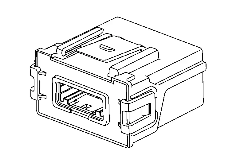
| 7. | Parking brake switch (automatic brake hold switch) | ||
| 8. | Chassis control module | Refer to Chassis Control Module. | |
Chassis Control Module
FUNCTIONS WITHIN THE SYSTEM
Chassis control module part controls automatic brake hold function according to the signals from each sensor, each switch and each control unit.
INDIVIDUAL FUNCTIONS WITHIN THE SYSTEM
-
Receives the signals required to activate the automatic brake hold function from each control unit.
-
Transmits the signals required to activate the automatic brake hold function to each control unit.
PARTS LOCATION
Refer to Component Parts Location.
Parking Brake Switch (Automatic Brake Hold Switch)
 NOTE:
NOTE:
-
Parking brake switch
 , automatic brake hold switch
 , and indicator
 are single unit.
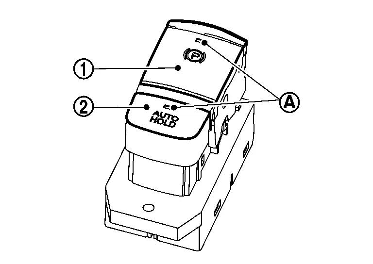
FUNCTIONS WITHIN THE SYSTEM
By operating automatic brake hold switch, turn ON/OFF automatic brake hold function.
 NOTE:
NOTE:
Automatic brake hold function retains the last state until the driver changes the option even if the ignition switch OFF.
INDIVIDUAL FUNCTIONS WITHIN THE SYSTEM
-
Turns ON/OFF automatic brake hold switch, and turns ON/OFF automatic brake hold function by chassis control module.
-
According to the control of chassis control module, automatic brake hold switch indicator turns ON/OFF.
-
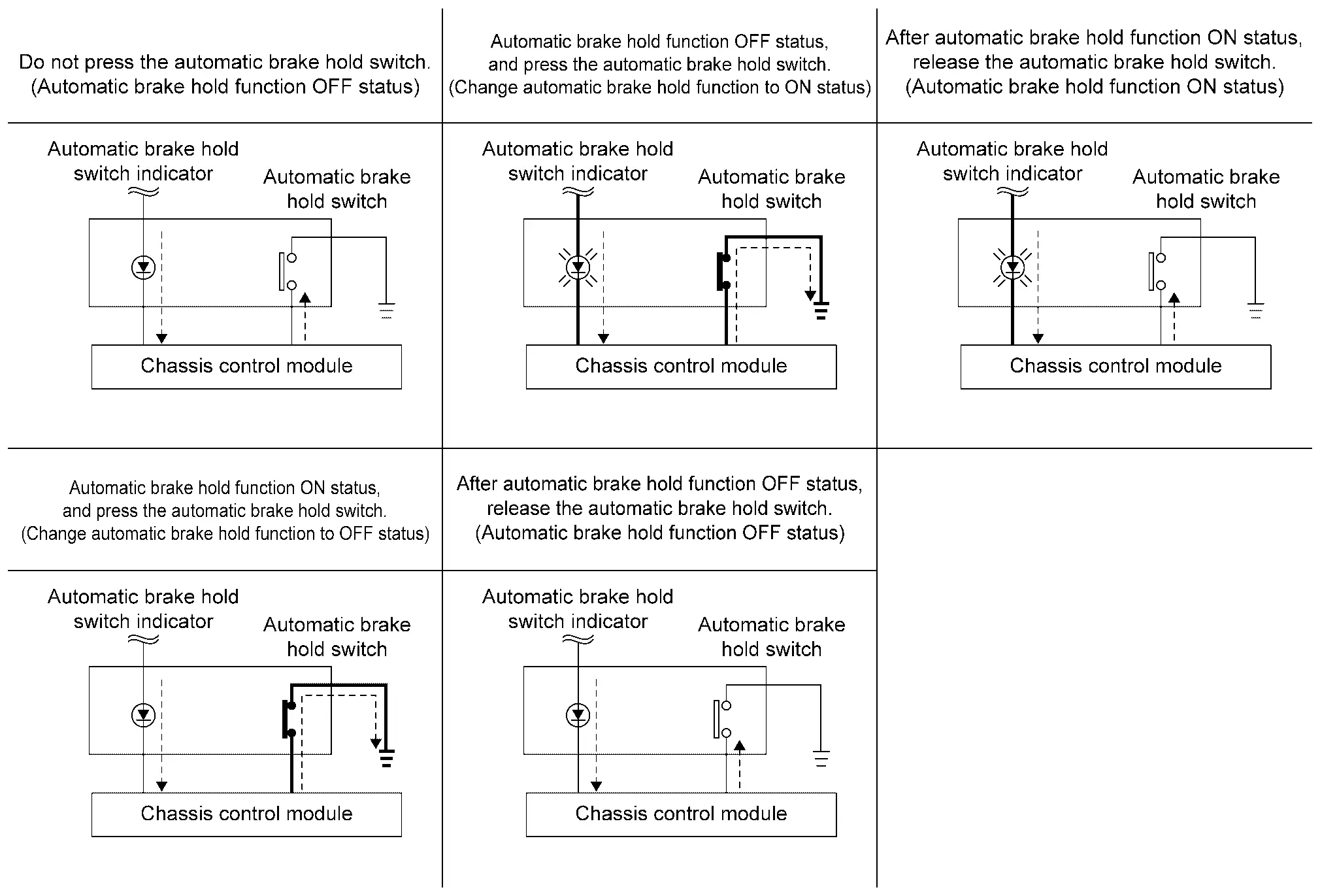
A normal open type is used for automatic brake hold switch.
-
If automatic brake hold switch is pressed when automatic brake hold function is OFF, automatic brake hold function turns ON. In addition, automatic brake hold switch indicator illuminates.
 NOTE:
NOTE:
Automatic brake hold function retains the last state until the driver changes the option even if the ignition switch is turned OFF.
-
If automatic brake hold switch is pressed when automatic brake hold function is ON, automatic brake hold function turns OFF. In addition, automatic brake hold switch indicator turns OFF. [If automatic brake hold indicator lamp (white or green) is ON, it turns OFF.]
 NOTE:
NOTE:
To turn OFF automatic brake hold function while the brakes are held by automatic brake hold, press automatic brake hold switch while depressing brake pedal.
PARTS LOCATION
Refer to Component Parts Location.
System Nissan Pathfinder Fifth generation
System Description
-
Automatic brake hold function is used for holding the brakes automatically when the vehicle is stopped by a brake operation.
-
Automatic brake hold function is used to reduce continuous brake pedal operations by the driver.
-
Automatic brake hold function is controlled by chassis control module.
-
Chassis control module receives information required for controlling via CAN communication and from each switch to control automatic brake hold function.
SYSTEM DIAGRAM
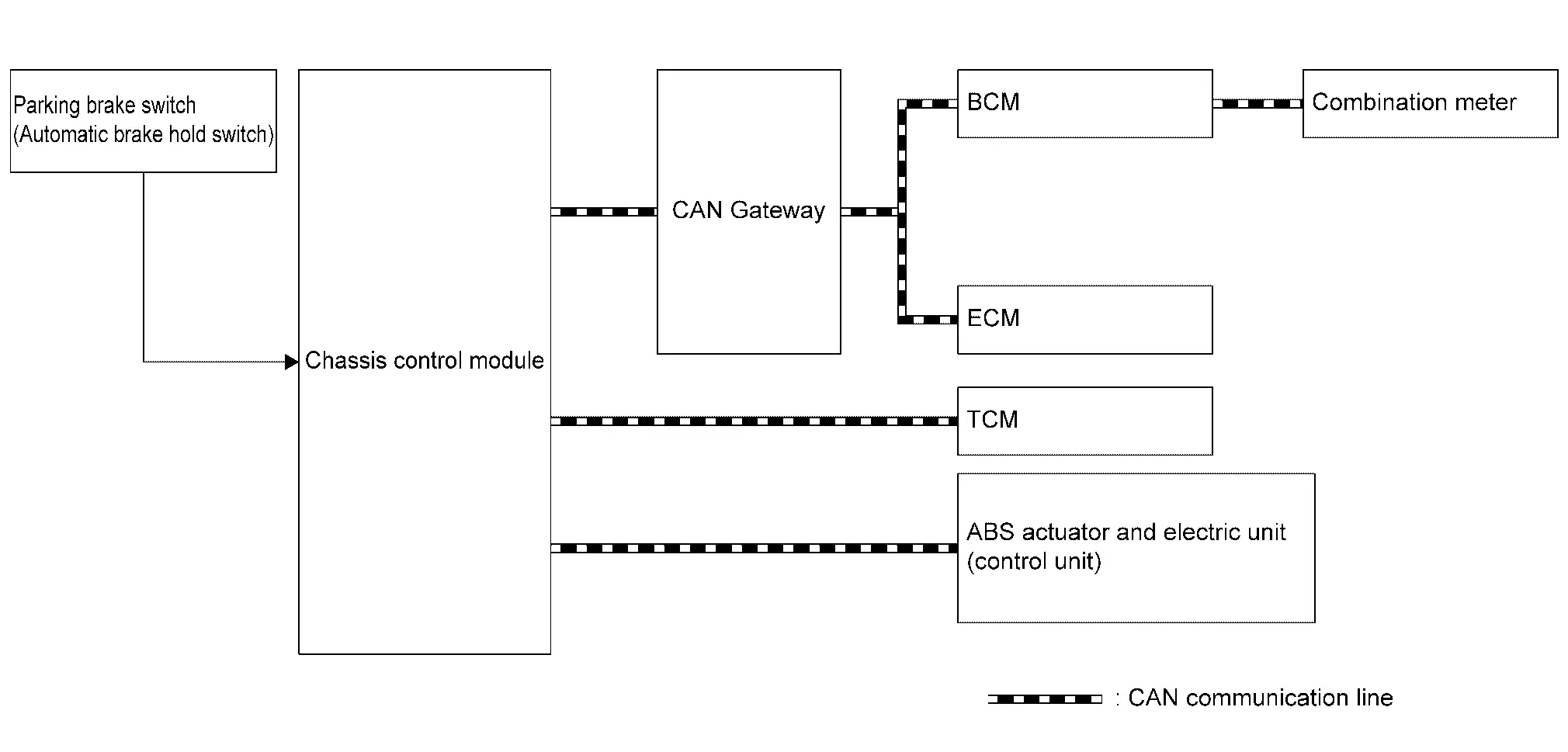
| Component | Signal description |
|---|---|
| ECM |
Mainly transmits the following signals to chassis control module via CAN communication.
|
| TCM |
Mainly transmits the following signals to chassis control module via CAN communication.
|
| ABS actuator and electric unit (control unit) |
Mainly transmits the following signals to chassis control module via CAN communication.
|
| Combination meter |
Mainly receives the following signals from chassis control module via CAN communication.
|
| BCM |
Mainly transmits the following signals to chassis control module via CAN communication.
|
| Chassis control module | Chassis Control Module |
|
Parking brake switch (automatic brake hold switch) |
Parking Brake Switch (Automatic Brake Hold Switch) |
OPERATION
Automatic Brake Hold Function ON (Operation Permitted)
If automatic brake hold switch is pressed when automatic brake hold function is OFF, automatic brake hold function turns ON. In addition, automatic brake hold switch indicator illuminates.
 NOTE:
NOTE:
Automatic brake hold function retains the last state until the driver changes the option even if the ignition switch OFF.
Automatic Brake Hold Function OFF (Operation Not Permitted)
If automatic brake hold switch is pressed when automatic brake hold function is ON, automatic brake hold function turns OFF. In addition, automatic brake hold switch indicator turns OFF. [If automatic brake hold indicator lamp (white or green) is ON, it turns OFF.]
 NOTE:
NOTE:
To turn OFF automatic brake hold function while the brakes are held by automatic brake hold function, press automatic brake hold switch while depressing brake pedal.
Standby
When all of the following conditions are satisfied, automatic brake hold function enters in the standby state, and automatic brake hold indicator lamp (white) illuminates.
-
Seat belt (driver side) is fastened
-
Electric parking brake is released
-
Shift position is not in the P
-
Automatic brake hold switch is ON
Operation
If all of the following conditions are satisfied in the standby state, automatic brake hold function operates, and the color of automatic brake hold indicator lamp changes from white to green. In addition, automatic brake hold display appears.
 NOTE:
NOTE:
Although the conditions are satisfied in the standby state, automatic brake hold function may not operate depending on how far brake pedal is depressed. When automatic brake hold function does not operate, depress brake pedal far enough until automatic brake hold indicator lamp (green) turns on.
-
Vehicle speed: 0 km/h (0 MPH)
-
Brake pedal is depressed
-
Automatic brake hold function is in the standby state [automatic brake hold switch indicator and automatic brake hold indicator lamp (white) are illuminated]
-
Not on a steep slope
-
Seat belt (driver side) is fastened
-
Electric parking brake is released
-
Shift position is not in the P
Release (Starting Vehicle)
If the following condition is satisfied while automatic brake hold function is being applied, automatic brake hold function is released. (The color of automatic brake hold indicator lamp changes from green to white.)
-
The vehicle is started
 NOTE:
NOTE:
-
Shift position is not in the P and N
-
Automatic brake hold function is operated by applying sufficient braking force to hold the Nissan Pathfinder vehicle in its place, so there are cases
-
When this hold function is maintained even if the accelerator pedal is depressed. In this situation, it is advised to depress the brake pedal first, then to turn OFF automatic brake hold switch. This will cancel the hold function.
Release (Automatic Brake Hold Switch)
If the following condition is satisfied while automatic brake hold function is being applied, automatic brake hold function is released. (Automatic brake hold indicator lamp turns OFF.)
-
Operate automatic brake hold switch while depressing brake pedal.
Release (Changing to Electric Parking Brake)
If any of the following conditions are met while automatic brake hold function is being applied, electric parking brake is operated automatically, and automatic brake hold function is released. (Automatic brake hold indicator lamp turns OFF.)
-
Operation of automatic brake hold function is continued for approximately 3 minutes
-
The electronic parking brake is applied manually
-
Seat belt (driver side) is unfastened
-
Door (driver side) is opened
-
Ignition switch OFF
-
A malfunction is detected in automatic brake hold function
-
Shift position is in the P
Parking
-
If shift position is in the P while automatic brake hold function is being applied, automatic brake hold function is released. (Automatic brake hold indicator lamp turns OFF.)
-
If the electric parking brake is applied while automatic brake hold function is being applied, automatic brake hold function is released. (Automatic brake hold indicator lamp turns OFF.)
Timing Chart
-
The vehicle is started while automatic brake hold function is being applied
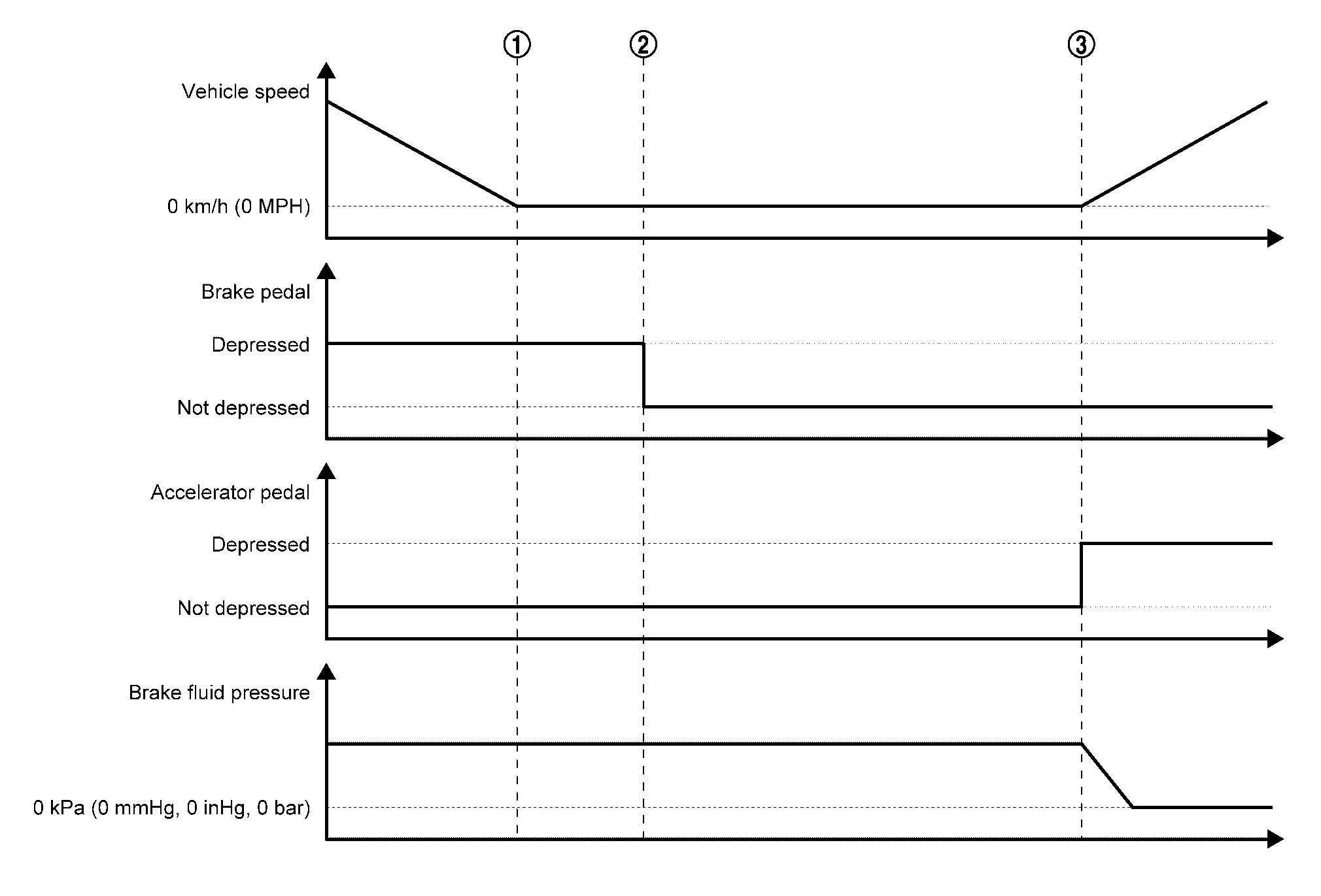

When the Nissan Pathfinder vehicle is stopped by a brake operation by the driver, maintaining of brake fluid pressure is started. 
Automatic brake hold function is applied (this function holds brake fluid pressure even after the driver has released brake pedal). 
When the driver performs starting operation, automatic brake hold function is released (brake fluid pressure is decreased). -
Changing the Nissan Pathfinder vehicle holding method to electric parking brake while automatic brake hold function is being applied
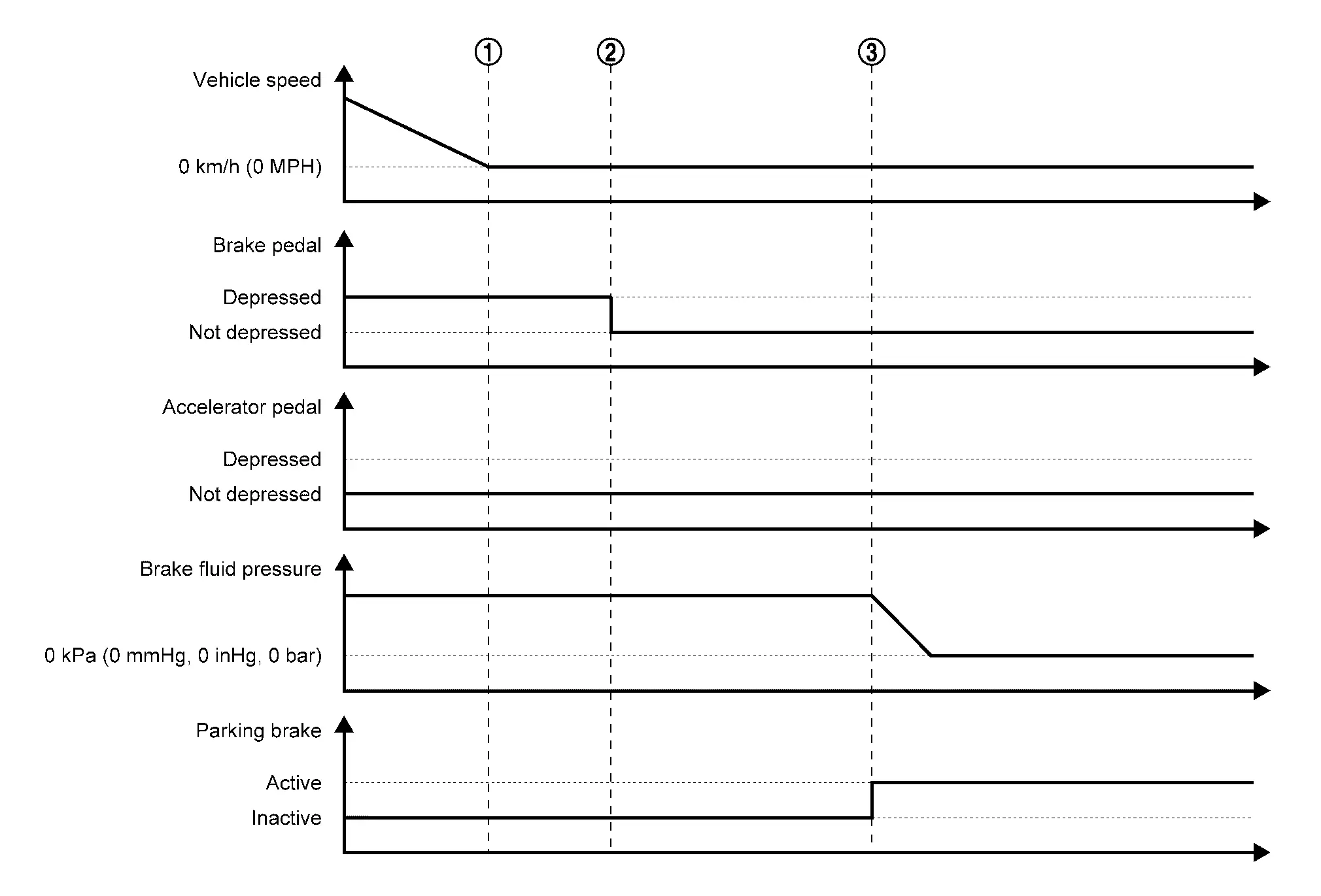

When the Nissan Pathfinder vehicle is stopped by a brake operation by the driver, maintaining of the brake fluid pressure is started. 
Automatic brake hold function is applied (this function holds brake fluid pressure even after the driver has released brake pedal). 
If the conditions for changing to electric parking brake are satisfied while automatic brake hold function is being applied, the method of holding the Nissan Pathfinder vehicle stopped is automatically changed to electric parking brake.
Fail-safe
Refer to Fail-safe.
Warning/indicator/chime List
Automatic Brake Hold Indicator Lamp
DESIGN/PURPOSE
-
Notifies the driver that automatic brake hold function can be operated (in the standby state). (white)

-
Notifies the driver that automatic brake hold function is applied. (green)
BULB CHECK
Not applicable
SYNCHRONIZATION WITH MASTER WARNING LAMP
Not applicable
OPERATION AT COMBINATION METER CAN COMMUNICATION CUT-OFF OR UNUSUAL SIGNAL
For actions on CAN communications blackout in the combination meter.
-
Full TFT meter: Refer to Fail-Safe.
-
7 inch information display: Refer to Fail-Safe.
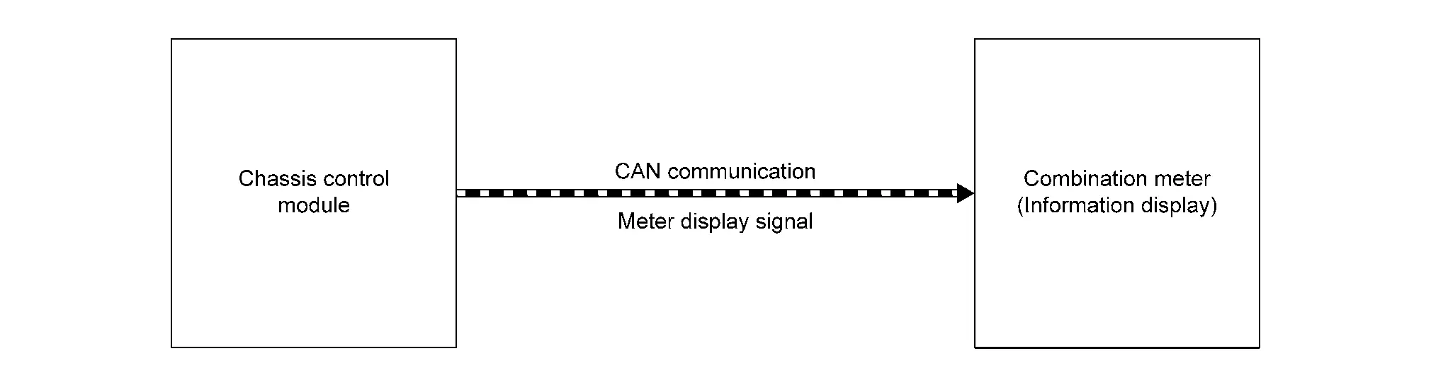
SYSTEM DIAGRAM
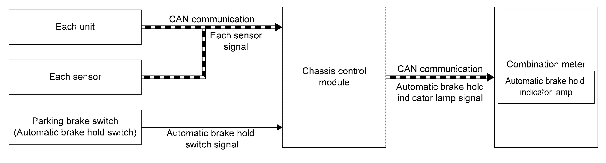
SIGNAL PATH
Automatic Brake Hold Function Standby State (Automatic Brake Hold Indicator Lamp: White)
-
Chassis control module receives automatic brake hold switch signal from automatic brake hold switch.
-
Chassis control module functions are turned ON by automatic brake hold switch signal. If the conditions to enter the standby state are satisfied, the module transmits automatic brake hold indicator lamp signal to combination meter via CAN communication.
-
Once receiving the automatic brake hold indicator lamp signal, the combination meter turns ON automatic brake hold indicator lamp (white).
Automatic Brake Hold Function Operating State (Automatic Brake Hold Indicator Lamp: Green)
-
If the operating conditions are satisfied and automatic brake hold function operates when automatic brake hold indicator lamp (white) is turned ON, chassis control module transmits automatic brake hold indicator lamp signal to combination meter via CAN communication.
-
Once receiving the automatic brake hold indicator lamp signal, the combination meter turns ON the automatic brake hold indicator lamp (green).
Automatic Brake Hold Function Release
-
If an automatic brake hold function operation is canceled by a starting operation by the driver, chassis control module transmits automatic brake hold indicator lamp signal to combination meter via CAN communication.
-
Once receiving automatic brake hold indicator lamp signal, the combination meter turns ON automatic brake hold indicator lamp (white).
LIGHTING CONDITION
Automatic Brake Hold Indicator Lamp (White)
-
All of the following conditions are satisfied (standby state)
-
Ignition switch ON
-
Automatic brake hold switch ON(automatic brake hold switch indicator is turn ON)
-
Automatic brake hold function not operated
-
Driver seat belt is fastened
-
Electric parking brake is release
-
Shift position is not in the P
-
-
Automatic brake hold function operation is canceled by starting operation by the driver
Automatic Brake Hold Indicator Lamp (Green)
Automatic brake hold function applied
SHUTOFF CONDITION
-
When any of the condition listed below is satisfied while the ignition switch ON
-
Automatic brake hold switch is OFF (automatic brake hold switch indicator is turn OFF)
-
Driver seat belt is not fastened
-
Electric parking brake operated
-
Shift position is in the P
-
Door (driver side) is opened
-
-
Ignition switch OFF
TIMING CHART
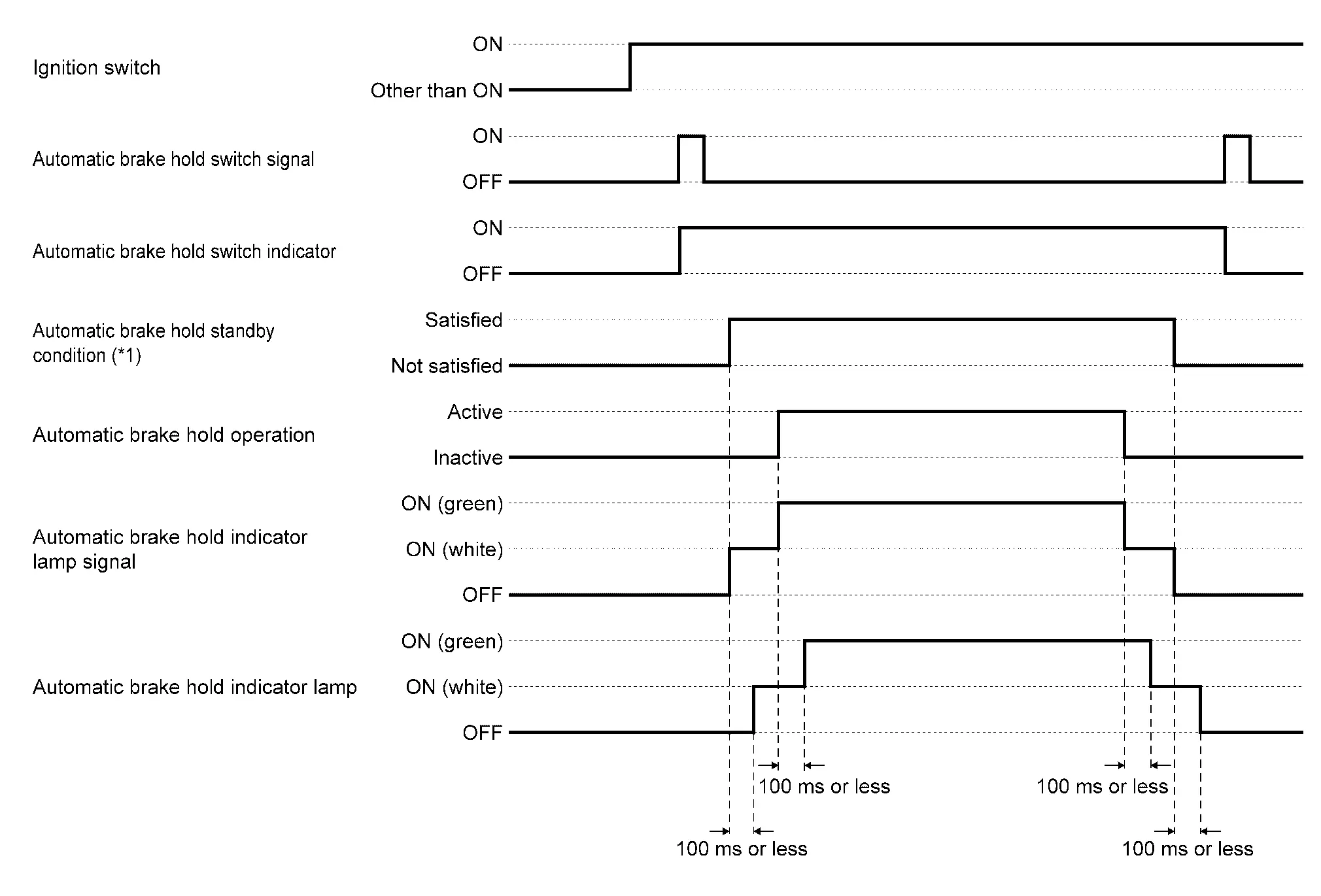
*1: For standby conditions of automatic brake hold function. Refer to System Description.
Information Display (combination Meter)
Chassis Control Warning
Refer to Chassis Control Warning.
Automatic Brake Hold Warning
DESIGN/PURPOSE
Notifies the driver when the vehicle is moved or may start moving while automatic brake hold function is being applied.
Warning Message
| Design | Warning message | Description |
|---|---|---|
| — | Press brake pedal to prevent rolling | When the Nissan Pathfinder vehicle moves or possibly moves while automatic brake hold function activates. |
| Caution Steep slope | When the automatic brake hold function activates on the steep slope. | |
| Steep Slope Apply foot brake | When the brake pedal is not depressed while the automatic brake hold function activates on the steep slope for 3 minutes approximately. | |
| Press brake to operate switch | When the automatic brake hold switch is pushed without depressing brake pedal while the automatic brake hold function activates. |
SYNCHRONIZATION WITH WARNING CHIME
| Warning message | — |
|---|---|
| Press brake pedal to prevent rolling | Applicable |
| Caution Steep slope | No |
| Steep Slope Apply foot brake | No |
| Press brake to operate switch | No |
SYNCHRONIZATION WITH MASTER WARNING LAMP
| Warning message | — |
|---|---|
| Press brake pedal to prevent rolling | Applicable |
| Caution Steep slope | No |
| Steep Slope Apply foot brake | No |
| Press brake to operate switch | No |
-
Full TFT meter: Refer to Master Warning Lamp.
-
7 inch information display: Refer to Master Warning Lamp.
SYSTEM DIAGRAM
WARNING MESSAGE DISPLAY CONDITION
When all of the following conditions are satisfied.
-
Automatic brake hold function applied
-
Vehicle is moved; vehicle may start moving; or a malfunction is detected in automatic brake hold function (chassis control module). Refer to Fail-safe.
Diagnosis System (chassis Control Module) Nissan Pathfinder
CONSULT Function
Chassis control module: Refer to CONSULT Function.

Nissan Pathfinder (R53) 2022-2026 Service Manual
System Description
Contact Us
Nissan Pathfinder Info Center
Email: info@nipathfinder.com
Phone: +1 (800) 123-4567
Address: 123 Pathfinder Blvd, Nashville, TN 37214, USA
Working Hours: Mon–Fri, 9:00 AM – 5:00 PM (EST)
